
herunterladen
GND
FB
V
SW
V
IN
SHDN
L
22 PH
LM3501-16
V
OUT
AGND
A1
CNTRL
C3
B1
C1
C2
B3
A2
A3
<0.3V
>1.1V
V
IN
2.7V - 5.5V
R2
24:
C
OUT
1 PF
Ceramic
C
IN
PF
Ceramic
Analog
Voltage
Control
User's Guide
SNVA084A–May 2004–Revised April 2013
AN-1318 LM3501 Evaluation Board
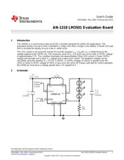
1 Introduction
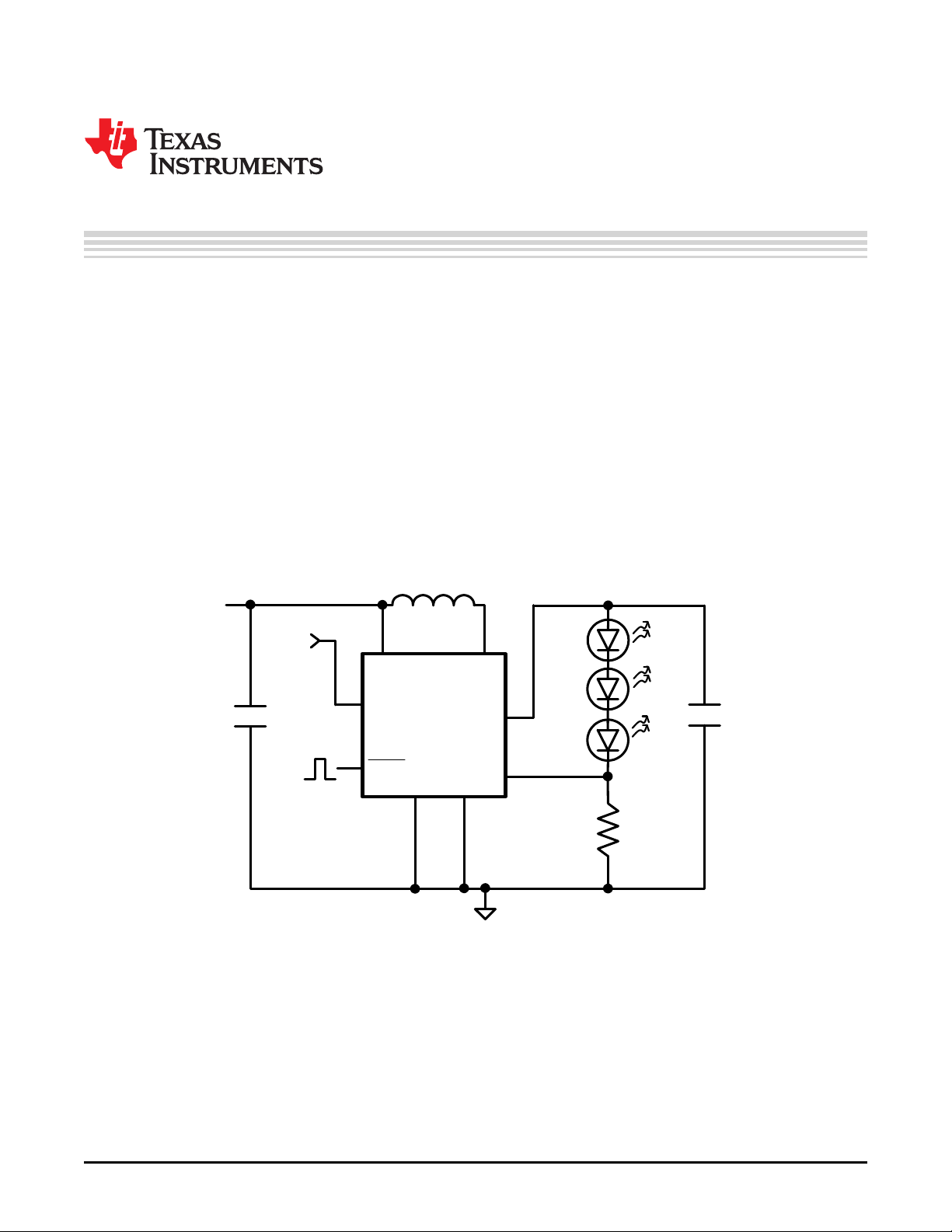
The LM3501 is a synchronous step-up DC/DC converter designed for white LED applications. The
evaluation board is set up to drive 3 standard V
F
white LEDs from a single Li-Ion battery. A fourth LED pad
(D4) is included for testing of up to 4 low V
F
white LEDs.
The LED current is set using the resistor R2 and the equation I
LED
= V
FB
/R2. V
FB
is determined by the
voltage applied to the CNTRL pin. The maximum value of V
FB
is 0.515V and occurs with a CNTRL voltage
of approximately 2.7V. This condition translates into approximately 20mA LED current. A lower CNTRL
voltage will translate into a lower V
FB
voltage and a lower LED current. The feedback voltage can be
calculated using the equation V
FB
= 0.191 × CNTRL. A CNTRL voltage of 125mV or greater turns the
LEDs on while a CNTRL voltage of 75mV or less turns the LEDs off. Please note that for correct operation
the SHDN pin must have a voltage greater than 1.1V applied to it.
2 Schematic
All trademarks are the property of their respective owners.
1
SNVA084A–May 2004–Revised April 2013 AN-1318 LM3501 Evaluation Board
Submit Documentation Feedback
Copyright © 2004–2013, Texas Instruments Incorporated
Verzeichnis
- ・ Blockdiagramm on Seite 1
- ・ Anwendungsbereich on Seite 3