
herunterladen
8
1
2
4
5
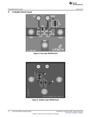
V
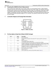
IN
SW
FB
EN
PGND
L1: 2.2 PH
V
OUT
C
OUT
10 PF
C
IN
4.7 PF
LM3676
V
IN
2.9V to 5.5V
MODE
3
6
NC
7
SGND
User's Guide
SNVA191D–December 2006–Revised April 2013
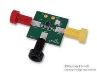
AN-1536 LM3676 Evaluation Board
1 Introduction
The LM3676 evaluation board is a working demonstration of a step down DC-DC converter. This
application note contains information about the evaluation board. For further information on buck converter
topology, device electrical characteristics, and component selection please refer to the LM3676 2-MHz
600-mA Step-Down DC-DC Converter With Mode Control (SNVS426).
2 General Description
The LM3676 converts high input voltages to lower output voltages with high efficiency through an inductor
based switching topology. The LM3676 has a mode-control pin that allows the user to select continuous
Forced PWM mode over the complete load range or an intelligent Auto, PFM-PWM, mode that changes
modes depending on the load. Setting the Mode pin low (<0.4V) places the LM3676 in Auto mode were
hysteretic PFM extends the battery life through reduction of the quiescent current to 16µA (typ.) during
light loads and system standby. When the Mode pin is high (>1.0V) the part offers superior efficiency
under high load conditions (>100mA) and the lowest output noise performance during Forced PWM. The
LM3676 is available in both fixed and adjustable output voltage options ranging from 1.0V to 3.3V in a 8-
lead non-pullback WSON package (3mm × 3mm).
3 Operating Conditions
• V
IN
range: 2.9V ≤ V
IN
≤ 5.5V
• Recommended load current: 0 mA ≤ I
OUT
≤ 600 mA
• Ambient temperature (T
A
) range: -30C to +85C
• Junction temperature (T
J
) range: -30C to +125C
4 Typical Application
Figure 1. Typical Application Circuit: Fixed Voltage
All trademarks are the property of their respective owners.
1
SNVA191D–December 2006–Revised April 2013 AN-1536 LM3676 Evaluation Board
Submit Documentation Feedback
Copyright © 2006–2013, Texas Instruments Incorporated
Verzeichnis