

herunterladen

User's Guide
SNVA400B–August 2009–Revised May 2013
AN-1976 LM5027 Evaluation Board
1 Introduction
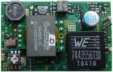
The LM5027 evaluation board is designed to provide the design engineer with a fully functional power
converter based on the Active Clamp Forward topology to evaluate the LM5027 controller. The evaluation
board is provided in an industry standard quarter-brick footprint.
The performance of the evaluation board is as follows:
Input Operating Range: 36 to 78V (100V peak)
Output Voltage: 3.3V
Output Current: 0 to 30A
Measured Efficiency: 90.5% @ 30A, 92.5% @ 15A
Frequency of Operation: 250 kHz
Board Size: 2.3 X 1.45 x 0.5 inches
Load Regulation: 1%
Line Regulation: 0.1%
Line UVLO, Hiccup Current Limit
The printed circuit board consists of 6 layers of 2 ounce copper on FR4 material with a total thickness of
0.050 inches. The unit is designed for continuous operation at rated load at <40°C and a minimum airflow
of 200 CFM.
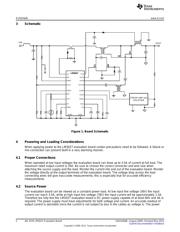
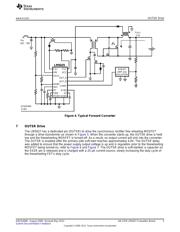
2 Theory of Operation
Power converters based on the Forward topology offer high efficiency and good power handling capability
in applications up to several hundred Watts. The operation of the transformer in a forward topology does
not inherently self-reset each power switching cycle; a mechanism to reset the transformer is required.
The active clamp reset mechanism is presently finding extensive use in medium level power converters in
the 50 to 200W range.
The Forward converter is derived from the Buck topology family, employing a single modulating power
switch. The main difference between the topologies are, the Forward topology employs a transformer to
provide input / output ground isolation and a step down or step up function.
Each cycle, the main primary switch turns on and applies the input voltage across the primary winding,
which has 12 turns. The transformer secondary has 2 turns, leading to a 6:1 step-down of the input
voltage. For an output voltage of 3.3V the required duty cycle (D) of the main switch must vary from
approximately 60% (low line) to 25% (high line). The clamp capacitor along with the reset switch reverse
biases the transformer primary each cycle when the main switch turns off. This reverse voltage resets the
transformer. The clamp capacitor voltage is Vin / (1-D).
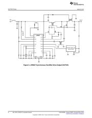
Feedback from the output is processed by an amplifier and reference, generating an error voltage, which
is coupled back to the primary side control through an optocoupler. The LM5027 voltage mode controller
pulse width modulates the error signal with a ramp signal derived from the input voltage. Deriving the
ramp signal slope from the input voltage provides line feed-forward, which improves line transient
rejection. The LM5027 also provides a controlled delay necessary for the reset switch. The evaluation
board can be synchronized to an external clock with a recommended frequency range of 275 to 300 kHz.
All trademarks are the property of their respective owners.
1
SNVA400B–August 2009–Revised May 2013 AN-1976 LM5027 Evaluation Board
Submit Documentation Feedback
Copyright © 2009–2013, Texas Instruments Incorporated
Verzeichnis