
herunterladen

User's Guide
SNVA495A–November 2011–Revised April 2013
AN-2170 LMR24210/20 Evaluation Board
1 Introduction
The LMR24210/20 Step Down Switching Regulator features all required functions to implement a cost
effective, efficient buck power converter capable of supplying up to 1.0A or 2.0A. The Constant On-Time
(COT) regulation scheme requires no loop compensation, results in a fast load transient response and
simple circuit implementation, this allows low component count, and consequently very small overall board
space. The regulator can function properly even with an all ceramic output capacitor network, and does
not rely on the output capacitor’s ESR for stability.
The LMR24210/20 has a wide input range from 4.5V-42V, making it suitable for a variety of applications
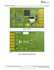
from automotive to power conditioning of unregulated sources. The LMR24210/20 Evaluation Board is
designed to provide the design engineer with a fully functional power converter to evaluate the
LMR24210/20 series of buck regulators.
2 Features
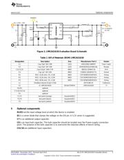
• 4.5V to 42V Input Voltage Range
• 3.3V Output Voltage (default setting)
• Up to 2000 mA Output Current (LMR24220)
• Up to 1000 mA Output Current (LMR24210)
• Switching Frequency of 500 KHz (default setting)
• PCB size: 46.8mm x 27.4mm
3 Enable Option
Install R4, R5 and D1 to enable the part at a desider input voltage. A voltage higher than 1.26V on the EN
pin will enable the device. Use the EN post to disable the device by pulling this node to GND. A logic
signal may be applied, to the post, to test startup and shutdown of the device. Leaving the EN pin open
will enable the device at internal UVLO level.
4 Adjusting the Output Voltage
The output voltage can be changed from 3.3V to another voltage by adjusting the feedback resistors using
Equation 1:
V
OUT
= V
FB
(1+(R1/R2)) (1)
Where V
FB
is 0.8V.
For more information on component selection and features, see the LMR24210 SIMPLE SWITCHER
®
42Vin, 1.0A Step-Down Voltage Regulator (SNVS738) and LMR24220 SIMPLE SWITCHER 42Vin, 2.0A
Stp-Dwn V-Reg in micro SMD (SNVS737) data sheets.
SIMPLE SWITCHER is a registered trademark of Texas Instruments.
All other trademarks are the property of their respective owners.
1
SNVA495A–November 2011–Revised April 2013 AN-2170 LMR24210/20 Evaluation Board
Submit Documentation Feedback
Copyright © 2011–2013, Texas Instruments Incorporated
Verzeichnis
- ・ Blockdiagramm on Seite 3
- ・ Anwendungsbereich on Seite 9
- ・ Elektrische Spezifikation on Seite 5 Seite 6