

herunterladen

User's Guide
SNVA505A–September 2011–Revised April 2013
AN-2193 LMR24220 Multi-Rail Reference Board
1 Introduction
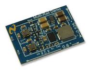
The LMR24220 multi-rail reference board implements an extremely compact solution. It is designed to
convert from 12 V or 24 V rails down to typical point-of-load voltages of 3.3V, 1.8V and 1.2V. This design
utilizes an LMR24220 Nano Regulator and two LMZ10501 Nano Modules to demonstrate a complete
solution for space constrained multi-rail applications.
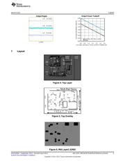
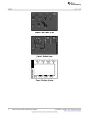
The complete solution size is 20.32 x 13.34 x 2mm with all components placed on a single side. The
board can be plugged into a standard 8-pin header with 100 mil spacing and total thickness less than 100
mils for ease of prototyping.
2 Features
• 5 V to 32 V Input Voltage Range
• 3.3 V / 1.8 V / 1.2 V Output Voltage Rails
• Up to 1000 mA Output Current Per Rail
• Small Solution Size (20.32 x 13.34 x 2mm)
• No External Compensation Required
3 Shutdown Operation
The reference board includes a resistor divider that implements an under voltage lockout (UVLO) that
disables the part when V
IN
is below 4 V. The threshold for the UVLO can be adjusted to suit the needs of
the application.
Ret = (V
UVLO
* 10K - 12.4K) (1)
The midpoint of the resistor divider is clamped to 4.3 V by diode D2 so that the EN pin voltage of the
LMR24220 does not exceed 7V. The midpoint is also tied to pin 8 of the header (EN). Use the EN pin to
disable the device by pulling this node to GND. A logic signal may be applied to the post to test startup
and shutdown of the device.
4 Adjusting the Output Voltage
The output voltage on the LMR24220 can be changed from 3.3 V to another voltage by adjusting the
feedback resistors using Equation 2.
R1 = [(V
OUT
/ V
FB
) -1] *R2 (2)
Where V
FB
is 0.8V.
The output voltage of either LMZ10501 can be changed from 1.8 V/1.2 V to another voltage by adjusting
the feedback resistors using Equation 3.
RB = [V
OUT
/ (5.875 - V
OUT
)] * RT (3)
For more information on component selection and features, see the LMR24220 and LMZ10501 data
sheets.
All trademarks are the property of their respective owners.
1
SNVA505A–September 2011–Revised April 2013 AN-2193 LMR24220 Multi-Rail Reference Board
Submit Documentation Feedback
Copyright © 2011–2013, Texas Instruments Incorporated
Verzeichnis