

herunterladen

© Semiconductor Components Industries, LLC, 2017 1 Publication Order Number:
April 2017- Rev. 1 AND9469/D
AND9469/D
LV8811G, LV8813G, LV8814J
Tuning Guide
Overview
The LV8811G, LV8813G, and LV8814J are 3-phase BLDC motor drivers
which are controlled with a single Hall sensor. This document contains
description about determination methods for external circuit constants, an
adjustment mechanism setting method, and applications proposal for more
stabilized operation.
More specifically, PWM pulse to DC conversion circuit and PH pin are
mentioned for determining the constants, the phase advance (lead angle) is
explained for the setting method with some specific examples, and reduction
method for start-up instability due to the hall amplitude are explained.
Contents
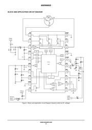
∙Block and application circuit diagram
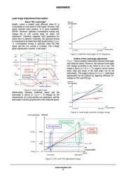
∙Lead angle adjustment description
About “Lead-angle”
Outline of Lead-angle adjustment
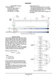
Input condition of the PH pins
Adjustment method
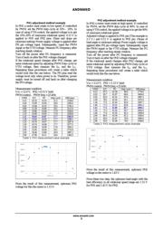
PH1 adjustment method example
PH2 adjustment method example
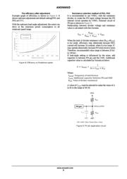
The efficiency after adjustment
Resistor of PH1 and PH2 selection method
∙Hall element description
About the output signal of Hall element
Output amplitude adjustment of Hall element by input bias
∙DC-PWM conversion description
Speed control by V
VTH
pin
Relations between V
VTH
voltage and output duty-cycle
Relations between V
VTH
voltage and input duty-cycle
Resistor selection method of V
VTH
external circuit
www.onsemi.com
APPLICATION NOTE
PACKAGE PICTURE
LV8811G and LV8813G
20-pin TSSOP with exposed pad
LV8814J
20-pin SSOP
Verzeichnis