herunterladen

Maxim > Design Support > Technical Documents > Reference Designs > Digital Potentiometers > APP 4195
Keywords: interface, spi clock, adc, example code, MAXQ2000
REFERENCE DESIGN 4195 INCLUDES: Tested Circuit Schematic Description Test Data Software
Selecting SPI Clock Modes for Interfacing the
MAX1132 ADC with the MAXQ2000 Microcontroller
By: Kien Mach
Mar 25, 2008
Abstract:
The MAXQ2000
can interface with the MAX1132 using different clock modes: 8-bit, 16-bit, or a
combination of both. This application note describes how to select an SPI™ clock mode that will optimize the
performance of the MAX1132. Included in the application note are complete schematics and microcontroller
firmware, as well as an example C program that was written and assembled for the IAR Embedded
Workbench® for MAXQ®.
Note: The suffix "-bar" (CS-bar) indicates the active-low functionality of the CS pin.
MAX1132 Overview
The MAX1132 is a 200ksps, 16-bit ADC. The MAXQ2000 can interface with the MAX1132 in a variety of SPI
clock modes: 8-bit, 16-bit, or a combination of both. To maximize the performance of the ADC, it is important
to determine which mode to use during early stages of development. It is obvious that a 16-bit ADC with 16
clock frames should use 16-bit mode; however, in a scenario where the ADC uses 24 clock frames, the SPI
clock mode must be evaluated closely. This application note provides test results for 8-bit mode, 16-bit mode,
and combination mode; the results indicate that combination mode is optimal when the MAX1132 uses 24
clock frames.
Hardware Overview
This application circuit utilizes the MAX1132EVKIT and MAXQ2000-KIT.
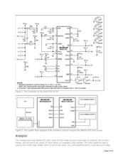
Figure 1 presents the MAX1132 EV kit schematic, and Figure 2 illustrates the configuration of the system. To
interface the MAX1132 EV kit with the MAXQ2000-KIT, connect SCLK, CS-bar, DOUT, and DIN from the
MAX1132 EV kit to the MAXQ2000-KIT, as shown in Figure 2. In addition, a +5V supply is applied on the
AV
DD
and AGND terminals of the EV kit. JU1 of the EV kit must be installed on 1–2 (ON) position. Apply an
analog signal up to +12V on JU2, and the rest of the jumpers are left open. SW3 of the MAXQ2000-KIT must
be turned off for proper operation of the system.
Page 1 of 5

