
herunterladen

Maxim > Design Support > Technical Documents > Reference Designs > Automotive > APP 4363
Maxim > Design Support > Technical Documents > Reference Designs > Power-Supply Circuits > APP 4363
Keywords: vacuum fluorescent display, fly back converter, flyback
REFERENCE DESIGN 4363 INCLUDES: Tested Circuit Schematic BOM Description Test Data
Vacuum Fluorescent Display (VFD) Reference
Design for Automotive Applications
Mar 26, 2009
Abstract:
This article
describes a vacuum fluorescent display (VFD) and some ideal applications for the
technology. The reference design then shows how to use a MAX15005 power-supply controller in a flyback
topology to obtain multiple output voltages for a vacuum fluorescent display.
Introduction
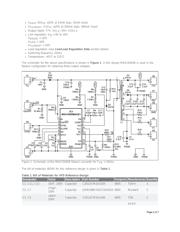
This reference design shows a solution for obtaining the drive voltage required for a vacuum fluorescent
display (VFD) power supply in automotive applications. The design includes the complete schematic, and
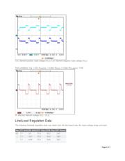
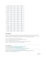
presents the bill of materials (BOM), load/line regulation measurements, and test results.
VFD Basics
A vacuum fluorescent display (VFD) is a type of display used commonly on consumer-electronics equipment
such as video cassette recorders, car radios, and microwave ovens. Unlike liquid crystal displays (LCDs), a
VFD emits a very bright light with clear contrast and can easily support display elements of various colors. The
technology is related to both the cathode ray tube and the nixie tube. Unlike LCDs, however, most VFDs
continue to function normally in subzero temperatures, making them ideal for outdoor devices in cold climates.
The VFD is composed of three basic electrodes—the cathode filaments, anodes (phosphor), and grids—under
a high-vacuum condition in a glass envelope. The cathode consists of fine tungsten wires, coated by alkaline
earth metal oxides which emit electrons. The grids are a thin metal mesh, which controls and diffuses
electrons emitted from the cathode. The anodes are conductive electrodes on which the phosphor is printed to
indicate characters, icons, or symbols. Electrons emitted from the cathode are accelerated with positive
potential applied to both grid and anode; upon collision with the anode the electrons excite the phosphor to
emit light. The desired illuminated patterns can be achieved by controlling the positive or negative potentials
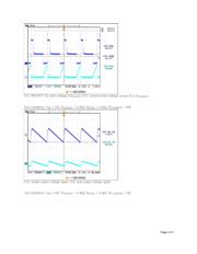
on each grid and anode. The anode and grid require a DC-regulated voltage to avoid flickering of the display.
For driving large VFDs, the cathode requires AC drive to prevent luminance slant, i.e., the difference in
brightness from one side of the display to the other. A frequency range of 20kHz to 200kHz is recommended
to avoid audible noise and flicker.
Design Specifications and Setup
This reference design features the MAX15005 power-supply controller optimized for automotive and VFD
applications. The application circuit is designed to meet the following specifications:
V
IN
: 9V to 16V continuous, 5.5V to 40V transient
V
ANODE
: 77V
DC
±10% at 18mA (typ), 58mA (max)
Page 1 of 7
Verzeichnis
- ・ Blockdiagramm on Seite 1 Seite 2
- ・ Technische Daten on Seite 1
- ・ Anwendungsbereich on Seite 1