
herunterladen

Maxim > Design Support > Technical Documents > Reference Designs > Display Drivers > APP 4369
Maxim > Design Support > Technical Documents > Reference Designs > LED Lighting > APP 4369
Maxim > Design Support > Technical Documents > Reference Designs > Power-Supply Circuits > APP 4369
Keywords: hb, high brightness, led, rgb, portable, projection, projector, high current, luminus, phlatlight
REFERENCE DESIGN 4369 INCLUDES: Tested Circuit Board Available Description Test Data
6A RGB LED Driver Reference Design for a
Portable Projector
By: Anil Baby, Senior Member of the Technical Staff
Jul 07, 2009
Abstract: This reference design for a 6A step-down LED driver is based on the MAX16821 device. This
circuit drives a single LED. This design includes the circuit specifications, circuit schematic, and circuit
description and performance.
Introduction
This is a reference design for a 6A step-down LED driver for a portable projector. The reference design
is based on the MAX16821, a PWM HB LED driver. This circuit drives a single LED; three MAX16821
devices are required to drive RGB LEDs.
LED Driver Specifications
Input supply voltage (V
IN
): 10V to 15V
Output voltage (V
LED
): 4.5V to 6V
Output current (I
LED
): 1.5A to 6A with analog control
Analog control voltage: 1.1V to 2.8V for 1.5A to 6A
Maximum LED on duty cycle: 50%
Maximum LED current rise/fall times: < 1µs
Maximum LED current ripple: < 15% at 6A
Inputs
V
IN
(J1 and J2 V
IN
+, J3 and J4 GND): 10V to 15V input power supply
On/Off (J8): leave open or drive +5V to enable the driver. Short for disabling the board.
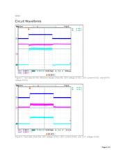
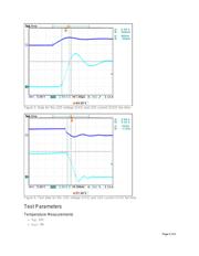
PWM input (J7): dimming PWM input. Connect a PWM signal with 3V to 5V amplitude. The source
should provide rise/fall times less than 500ns with a 300pF load so that the PWM input can drive
Q1 and Q7. As output can rise/fall within 1µs, any PWM period three to four times higher than 1µs
can be used.
LED current control (J6): LED current adjust input. Apply 1.1V to 2.8V to adjust LED current from
1.5A to 5A.
Outputs
Page 1 of 6
Verzeichnis
- ・ Blockdiagramm on Seite 2
- ・ Technische Daten on Seite 1