
herunterladen

Click here for an overview of the wireless
components used in a typical radio
transceiver.
Maxim > Design Support > Technical Documents > Tutorials > Wireless and RF > APP 5100
Keywords: layout, pcb, mixed signal, rf pcb, board design, board layout, wireless, printed circuit board, stripline,
transmission line
TUTORIAL 5100
General Layout Guidelines for RF and Mixed-Signal PCBs
By: Michael Bailey
Sep 14, 2011
Abstract: This application note provides guidelines and suggestions for RF printed-circuit board (PCB) design and
layout, including some discussion of mixed-signal applications. The material provides "best practices" guidance, and
should be used in conjunction with all other design and manufacturing guidelines that may apply to particular
components, PCB manufacturers, and material sets as applicable.
This application note applies to all of Maxim's wireless products. For more information, please select a wireless or RF
product.
Table of Contents
Introduction
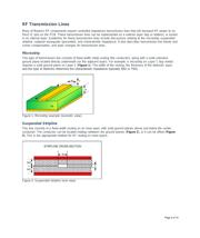
RF Transmission Lines
Microstrip
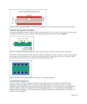
Suspended Stripline
Coplanar Waveguide (Grounded)
Characteristic Impedance
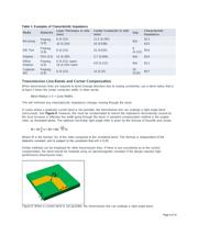
Transmission Line Bends and Corner Compensation
Layer Changes for Transmission Lines
Signal Line Isolation
Ground Planes
Special Consideration on Bias and Ground Layers
Power (Bias) Routing and Supply Decoupling
Selection of Decoupling or Bypass Capacitors
Bypass Capacitor Layout Considerations
Grounding of Shunt Connected Components
IC Ground Plane ("Paddle")
Introduction
This application note provides guidelines and suggestions for RF printed-circuit board (PCB) design and layout,
including some discussion of mixed-signal applications, such as digital, analog, and RF components on the same
PCB. The material is arranged by topic areas and provides "best practices" guidance. It should be used in
conjunction with all other design and manufacturing guidelines that may apply to particular components, PCB
manufacturers, and material sets as applicable.
Page 1 of 10