

herunterladen

Maxim > Design Support > Technical Documents > Reference Designs > Amplifier and Comparator Circuits > APP 4322
Maxim > Design Support > Technical Documents > Reference Designs > Battery Management > APP 4322
Maxim > Design Support > Technical Documents > Reference Designs > Power-Supply Circuits > APP 4322
Keywords: Battery Emulator, simulated load, lithium-ion, li-ion, LI+, load testing, charger, fast charge
REFERENCE DESIGN 4322 INCLUDES: Tested Circuit Schematic Description Test Data
Simplified Lithium-Ion (Li+) Battery-Charger Testing
By: Alfredo H. Saab, Applications Engineering Manager
Shasta Thomas, Applications Engineer
Dec 10, 2008
Abstract:
Because the charging
process for Li+ batteries can take an hour or longer, testing a Li+ battery
charger using its natural load (i.e., a battery) is time consuming and inconvenient. This application note
presents a simple circuit for simulating the behavior of a Li+ battery, thus providing a more convenient method
for testing Li+ battery chargers than using real batteries.
A similar version of this article was featured in Maxim's Engineering Journal, vol. 64 (PDF, 1.99MB).
Introduction
Lithium-ion (Li+) batteries are more delicate than other battery chemistries and have little tolerance for abuse.
Consequently, Li+ battery chargers are complex circuits, requiring highly accurate current and voltage settings.
If these accuracy requirements are not met, the charger may fail to completely charge the battery, severely
reduce battery life, or otherwise degrade battery performance.
Given the demands imposed on Li+ chargers, it is critical that charger designs be tested thoroughly and
stepped through their entire operating range. However, testing a Li+ charger with its natural load (i.e., a Li+
battery) can be time consuming and impractical in laboratory and production environments. To simplify the
process, this article presents a battery-emulation circuit for accelerated, realistic testing of Li+ battery chargers
without actual batteries.
CC-CV Charging
The Li+ battery-charging process requires medium-accuracy constant-current (CC) charging in a first phase,
transitioning to high-accuracy constant-voltage (CV) charging in a second phase.
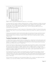
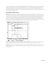
Figure 1 illustrates the V-I characteristics of a modern CC-CV integrated circuit (the MAX1737) used for a Li+
battery charger. This type of IC is at the heart of all Li+ battery chargers in consumer products. The CC
(between 2.6V and 4.2V battery voltage) and the CV (4.2V) regions are clearly shown.
Page 1 of 7
Verzeichnis
- ・ Blockdiagramm on Seite 1
- ・ Anwendungsbereich on Seite 1