


herunterladen
More Information
- Wireless Home
- Application Notes and Tutorials
- EV Kit Software
- Technical Support
Click here for an overview of the wireless
components used in a typical radio
transceiver.
Maxim > Design Support > Technical Documents > Reference Designs > Microcontrollers > APP 5150
Maxim > Design Support > Technical Documents > Reference Designs > Temperature Sensors and Thermal Management > APP 5150
Maxim > Design Support > Technical Documents > Reference Designs > Wireless and RF > APP 5150
Keywords: wireless, remote, temperature sensor, temperature monitoring, temperature data logging
REFERENCE DESIGN 5150 INCLUDES: Tested Circuit Schematic Description Software
Simple Wireless Temperature Monitor Also Has Data-
Logging Capabilities
By: Tom Au-Yeung, Director of Customer Applications
Wilson Tang, Member of Technical Staff
May 14, 2012
Abstract: This design idea shows how you can design a simple wireless
temperature-monitoring system with data-logging capabilities by using a local
temperature sensor and an ASK transmitter and receiver pair.
You can design a simple wireless temperature-monitoring system with data-
logging capabilities by using a local temperature sensor and an ASK transmitter
(Figure 1) and receiver pair. A MAXQ® microcontroller processes and displays
the temperature reading to the user (Figure 2). The microcontroller's onboard
UART also allows for data-logging applications.
In Figure 1, the MAX6577 is a local temperature sensor that detects the
ambient temperature at the device. The output of the MAX6577 is a square
wave with a frequency proportional to temperature in units of Kelvin. The
MAX1472 is the ASK transmitter and modulates the signal on to the carrier
frequency of 315MHz.
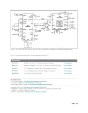
In Figure 2, the MAX1470 is the ASK receiver and demodulates the signal at the corresponding carrier frequency.
The output signal's frequency is measured with a frequency counter. The configured scalar multiplier is 1K/Hz when
TS1 is connected to GND and TS0 connected to V
DD
. This scalar multiplier is configurable with pins TS1 and TS0
(Figure 1).
The MAX9075 is a comparator connected to the MAX1470's RSSI with internal peak detector pin. The external RC
follows the peak power of the received signal. This is compared with a predetermined voltage level generated by a
resistor voltage divider. Lab experiments show that a threshold of approximately 1.57V generates a valid output on the
DATAOUT pin without receiving false readings. Adjust this threshold to the proper level for optimal performance. The
comparator's output is low when a weak or invalid signal is received and high when the received signal is adequate.
Next the MAXQ2000, a MAXQ-based microcontroller, measures the signal frequency and displays the value using its
integrated timer/counters and LCD driver peripherals. A counter tracks the number of rising-edge transitions on the
input temperature signal, while a timer tracks the elapsed time. After the timer's 1-second period elapses, an interrupt
occurs. At this moment, the counter value is read, converted to Celsius, and displayed on the LCD. Next, the counter
is reset to 0 to restart the process. The timer is automatically reloaded once the timer interrupt occurs. The resulting
temperature is also output by UART0. A handheld frequency counter is used to verify the temperature reading.
The microcontroller monitors the signal power through P6.0, configured as a general-purpose input pin. When the
Page 1 of 3
Verzeichnis
- ・ Blockdiagramm on Seite 1
- ・ Anwendungsbereich on Seite 1