

herunterladen
© Semiconductor Components Industries, LLC, 2012
March, 2012 − Rev. 1
1 Publication Order Number:
EVBUM2086/D
NB7L32MMNEVB
NB7L32M Evaluation Board
User's Manual
Description
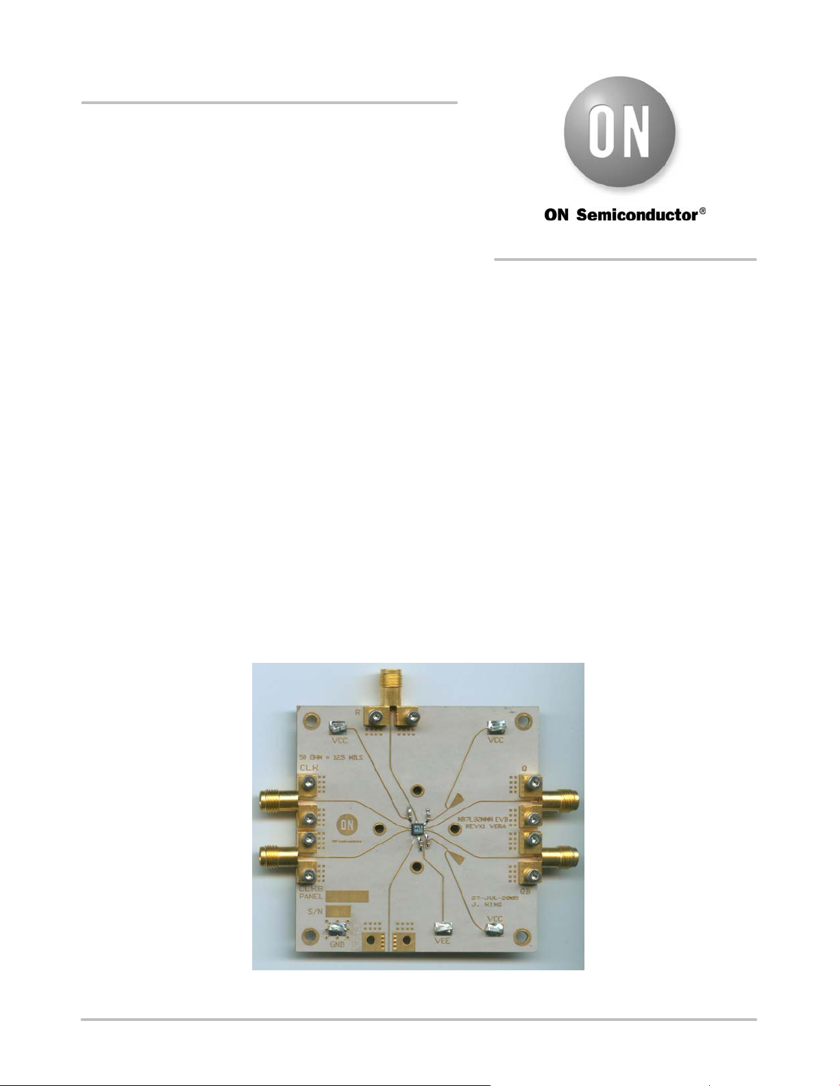
This document describes the NB7L32M evaluation board
and the appropriate lab test setups (See Figure 1). It should
be used in conjunction with the NB7L32M data sheet which
contains full technical details on the device specification and
operation.
The evaluation board is designed to facilitate a quick
evaluation of the NB7L32M GigaCommt Clock Driver.
The NB7L32M is designed to support the distribution of
clock/data signals at high operating frequencies and
produces two equal differential clock/data outputs from a
single input clock/data. The Current Mode Logic (CML)
output ensures minimal noise and fast switching edges.
The evaluation board is implemented in two layers for
higher performance.
Board Lay−up
The board is implemented in two layers and provides a
high bandwidth 50 W controlled impedance environment for
higher performance. The first layer or primary trace layer is
5 mils thick Rogers RO6002 material, which is engineered
to have equal electrical length on all signal traces from the
NB7L32M device to the sense output. The second layer is
32 mils thick copper ground plane.
What measurements can you expect to make?
With this evaluation board, the following measurements
could be performed in single−ended or differential modes of
operation:
• Jitter
• Output Skew
• Gain/Return Loss
• Eye Pattern Generation
• Frequency Performance
• Output Rise and Fall Time
• V
CMR
(Common Mode Range)
This Evaluation Board User’s Manual Contains:
• Information on NB7L32MMNEVB Evaluation Board
• Appropriate Lab Setup
• Bill of Materials
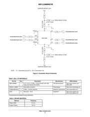
Figure 1. NB7L32M Evaluation Board
http://onsemi.com
EVAL BOARD USER’S MANUAL
Verzeichnis