


herunterladen
Semiconductor Components Industries, LLC, 2012
October, 2012 − Rev. 2
1 Publication Order Number:
EVBUM2142/D
NCP1031POEEVB
NCP1031 6.5 W POE DC-DC
Converter Evaluation Board
User's Manual
Introduction
A solution to one aspect of Power Over Ethernet (POE) is
presented here utilizing the ON Semiconductor NCP1031
series of monolithic, high voltage switching regulators with
internal MOSFET. The evaluation board user’s manual
provides details for constructing an inexpensive, high
efficiency, 5.0 V DC power supply with a power output of
5.0 to 6.5 W, (output power is conversion mode dependent
− see DC to DC Converter Operation description below).
The associated input circuitry for responding to POE
detection and classification protocol is also included.
ON Semiconductor also can provide a demonstration PC
board with this circuitry upon request.
POE Background
As a result of IEEE Standard 802.3AF, it is now possible
to inject DC power through Ethernet data transmission lines
to power Ethernet communication devices as long as the end
power requirement is less than 13 W. The parametric details
of DC power transmission and the associated terminology is
outlined in this IEEE document. POE consists of two power
entities: Power Sourcing Equipment (PSE) and Powered
Devices (PDs). The PSEs typically provides 48 Vdc
nominal to the LAN cables while the PDs are small DC−DC
converters at the load end of the cables which transform the
48 V to logic levels such as 5.0 Vdc or 3.3 Vdc or both, to
power the communications equipment. The PDs should be
able to operate with a maximum average input power of
12.95 W, and should be able to tolerate an input voltage
range of 36 to 57 Vdc. In addition, a certain “protocol” is
required in which the PD is detected (Signature Mode) and
then classified (Classification Mode) according to its
maximum power level.
Signature Detection:
The upstream PSE equipment detects the PD by injecting
two different voltages between 2.8 and 10 Vdc into the PD
input terminals. If the detected impedance of the PD as
measured by the V/I slope is above 23.7 kW, and below
26.25 kW, the PD is considered present. If the impedance is less
than 15 k, or greater than 33 k, the PD is considered not present,
and no further voltage will be applied.
Classification Mode:
To classify the PD according to its intended power level,
the PSE will again source a voltage between 14.5 and
20.5 Vdc to the PD. The classification is determined by the
current drawn by the PD upon application of this voltage,
and is summarized in the Table 1.
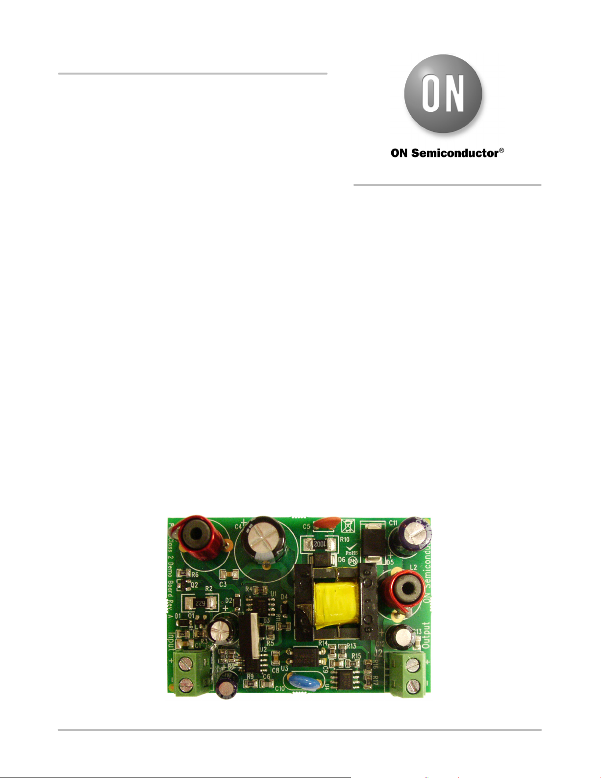
Figure 1. NCP1031 Evaluation Board
http://onsemi.com
EVAL BOARD USER’S MANUAL
Verzeichnis