
herunterladen
© Semiconductor Components Industries, LLC, 2013
September, 2013 − Rev. 0
1 Publication Order Number:
EVBUM2213/D
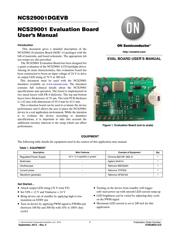
NCS29001DGEVB
NCS29001 Evaluation Board
User'sManual
Introduction
This document gives a detailed description of the
NCS29001 Evaluation Board (SOIC-14 package) with the
bill of materials, and board schematic. The appropriate lab
test setups are also provided.
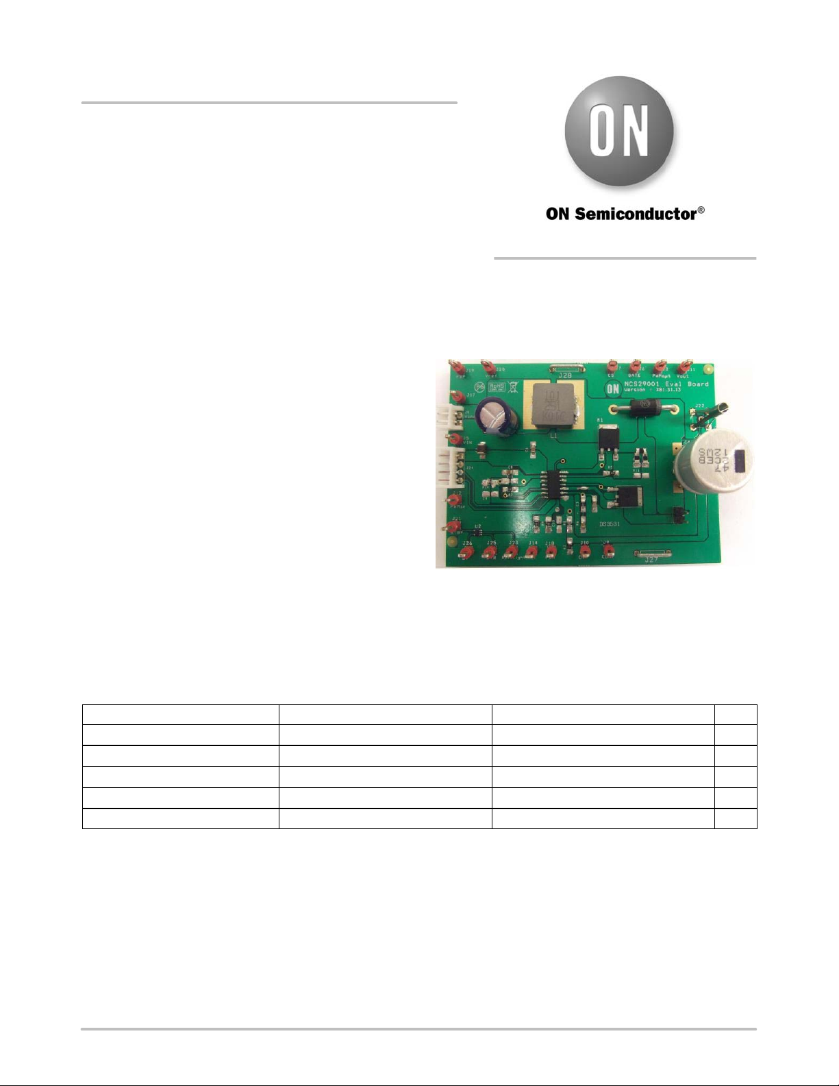
The NCS29001 Evaluation Board has been designed for
a quick evaluation of the NCS29001 LCD backlight driver.
Among its main characteristics, this evaluation board has
been constructed to boost an input voltage of 24 V to drive
an output LED string of 76 V at 200 mA.
This document must be used with the NCS29001
datasheet available on www.onsemi.com. The datasheet
contains full technical details about the NCS29001
specifications and operation. The board is implemented in
two metal layers with FR-4 dielectric. The top and bottom
layers have thicknesses of 35 mm. The total PCB thickness
is 1.62 mm with dimensions of 95.4 mm by 63.5 mm.
This evaluation board can be used to evaluate the device
performance and it allows the user to place the NCS29001
device in a real application environment. While the intention
is to evaluate the device according to datasheet
specifications, it is important to take into account the
additional circuitry inherent to the setup which can affect
performance.
Figure 1. Evaluation Board (not to scale)
EQUIPMENT
The following table details the equipment used in the context of this application note manual.
Table 1. EQUIPMENT
Description Main Features Example of Equipment Qty.
Regulated Power Supply
25 V / 5 A capability or greater
Chroma 62012P−600−8
1
Multimeter
−
Agilent 34401A
1
Oscilloscope
−
Tektronix MSO2024
1
Current probe
−
Tektronix TCP202
1
Waveform generator
−
Tektronix AFG3102
1
Get Started…
• Attach output LED string (76 V total VF)
• Set VIN = 12 V and Vinductor = 24 V
• Bring device out of standby by applying high to low
transition on STBY pin
• Turn on device by applying PWM signal to PWMin pin
(between 100 Hz and 300 Hz with 10% to 100% duty
cycle)
• Turning on the device from standby will trigger
soft−start power up with smooth LED current ramp up
• LED brightness can be varied by adjusting duty cycle
on the PWM signal
• Maximum LED current is set to 200 mA for this
application
http://onsemi.com
EVAL BOARD USER’S MANUAL
Verzeichnis