
herunterladen
© Semiconductor Components Industries, LLC, 2015
July, 2015 − Rev. 0
1 Publication Order Number:
EVBUM2304/D
NCS36000GEVB
NCS36000 PIR Sensor
Evaluation Board
User's Manual
General
The Passive InfraRed (PIR) sensor evaluation board is designed to
evaluate the NCS36000, a fully integrated mixed-signal CMOS device
designed for low-cost passive infrared controlling applications. This
device integrates two low-noise amplifiers and a LDO regulator to
drive the sensor. The output of the amplifiers goes to a window
comparator that uses internal voltage references from the regulator.
The detection logic processes the output from the window comparator
and provides the output to the ‘OUT’ pin. A blinking LED indicates
startup and depending on the status of the ‘LED_EN’ pin the LED also
lights up when a valid movement is detected.
The EVB can be powered from a micro-USB cable connected to
a host-USB interface (e.g. pc). Alternatively an external power source
ranging from 4–9 V can be connected to pins ‘GND’ and ‘+’ of the 3
pins header ‘H1’.
General Usage
Power the evaluation board by plugging a micro-USB cable in
connector USB1 or by connecting an external power source with
a voltage ranging 4–9 V DC between ‘GND’ and ‘+’ terminal of pin
header H1.
After power up, the LED1 starts blinking. This lasts about
30 seconds depending on the ‘TIMER’ setting. When LED1 stops
blinking, the evaluation board is ready for normal operation.
There are two potentiometers on the board. One is labeled
‘SENSITIVITY’ which controls the gain of the band-pass filter. For
more information, see the ‘Filter characteristics’ section. The other
potentiometer is labeled ‘TIMER’ and controls the system oscillator
frequency. Its setting affects the logic subsystems that determine if
a movement is detected or not. For more information see the ‘Timing
characteristics’ section.
Wave your hand above the Fresnel lens. This motion is detected
when LED1 turns on. Simultaneously the logic level on the ‘OUT’ pin
of pin header ‘H1’ is high. ‘OUT’ is the output of the digital signal
processing block. It is possible to monitor the input of the window
comparator by probing the ‘OP2_O’ test pin ‘TP2’.
The total current consumption of the application can easily be
measured by removing the 0 W jumper marked ‘CURR’ and putting an
Amp meter in series.
Jumpers JP3 (MODE) and JP5 (LED Enable) has following
function:
Table 1. JUMPER SETTING
Jumper State Function
MODE Open Dual Pulse Mode
MODE Close Single Pulse Mode
LED EN Open LED will Not Toggle*
LED EN Close LED Toggles after Motion Detected
*During start-up LED1 will blink for about 30 s. After this initialization period the
LED is disabled.
www.onsemi.com
EVAL BOARD USER’S MANUAL
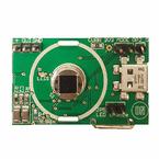
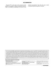
Figure 1. Top View of Evaluation Board
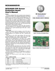
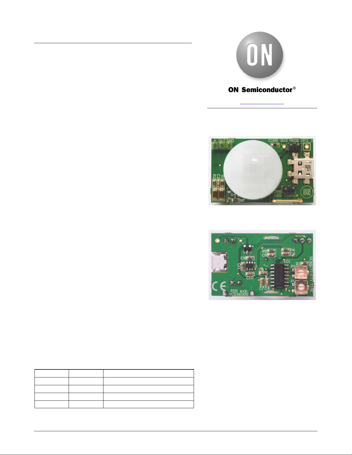
Figure 2. Bottom View of Evaluation Board