


herunterladen
© Semiconductor Components Industries, LLC, 2015
April, 2015 − Rev. 1
1 Publication Order Number:
AND8299/D
AND8299/D
EMC Tests and PCB
Guidelines for Automotive
Linear Regulators
Introduction
Electromagnetic compatibility (EMC) is important for the
functionality and security of electronic devices. Today’s
designers must deal with steadily increasing system
frequencies, changing power limits, high-density layouts
required by more complex systems, and the ever-present
need for low manufacturing cost. Therefore, it is necessary
to optimize EMC.
Linear regulators supply several types of loads including
microcontrollers, one of the key devices in automotive
applications.
This document concentrates on EMC for automotive
basic knowledge, test methods at the IC level and
ON Semiconductor standards. PCB guide lines are included
to prevent any board effect or external coupling.
Definition of EMC
Electromagnetic compatibility (EMC) is the capacity of a
piece of equipment to work properly in its normal
environment, and not create electrical disturbances that
would interfere with other equipment.
Electromagnetic susceptibility (EMS) is the level of
resistance to electrical disturbances such as electromagnetic
fields and conducted electrical noise.
Electromagnetic interference (EMI) is the level of
conducted/radiated electrical noise created by the
equipment.
Standards are addressing EMS or EMI issues for every
type of application area. These standards apply to finished
equipment.
EMC tests must be performed on the sub-systems in order
to evaluate and optimize applications for EMC
performances. Standards for IC-level EMC testing have
existed since 2003. Two Standards are commonly used:
IEC62132−4 (Direct Power Injection or DPI) for EMS and
the IEC61967−4 (1 W/150 W method)
Definition of Noise
Susceptibility to radio frequency interference is becoming
a major concern for integrated circuits, with the propagation
of new and powerful electromagnetic sources. Electrostatic
discharges, mains transients, switching of high currents and
voltages or radio frequency (RF) generators are just some of
the causes of electromagnetic interference. EMI can be
transferred by electromagnetic waves, conduction, and
inductive/capacitive coupling.
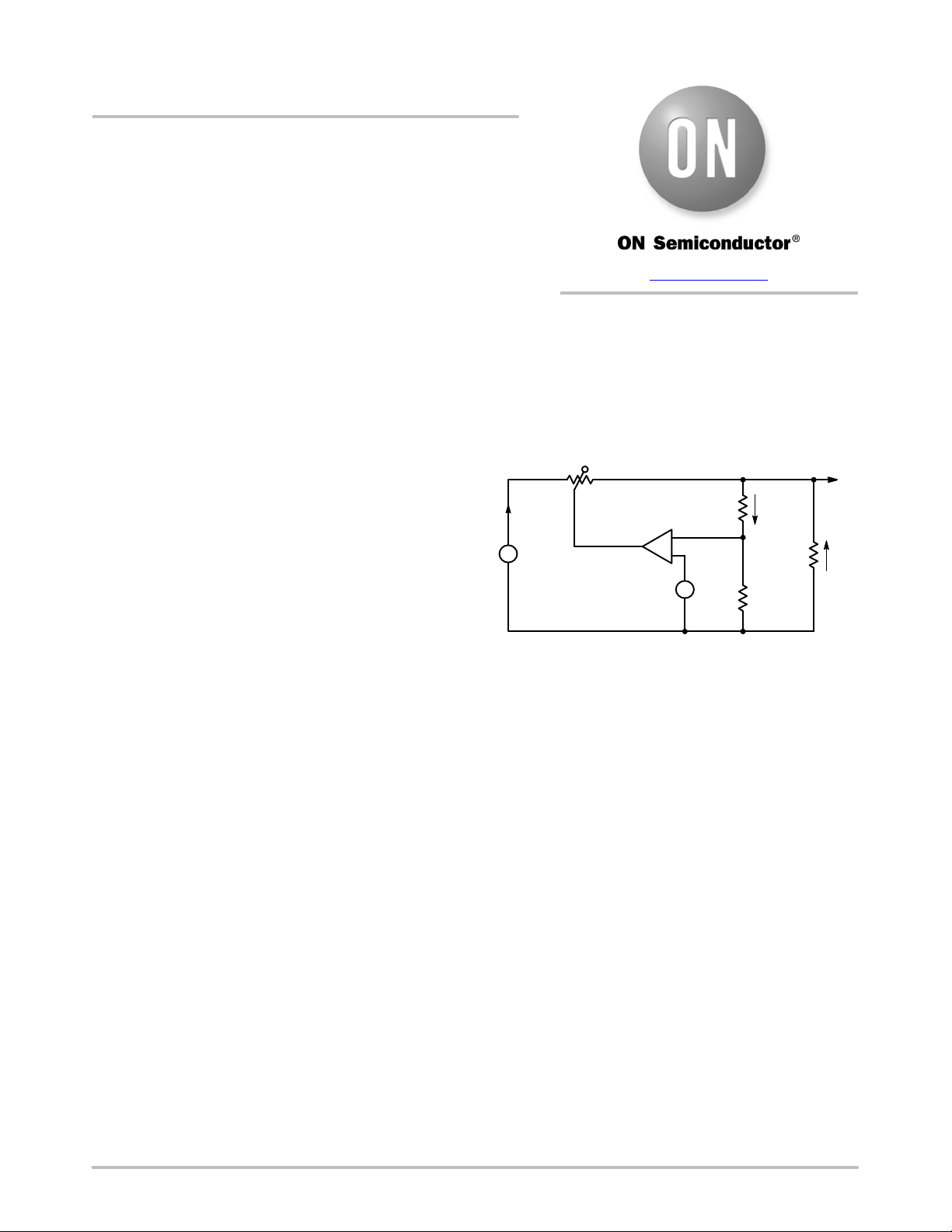
The Linear Regulators Architecture
The linear approach is often considered for low output
noise generation.
Figure 1. Linear Power Supply
-
+
Linear Pass Element
V
IN
12 V
1 A
ErrAmp
+
+
V
ref
R
low
R
up
R
load
5 V
1 A
V
OUT
However, efficiency is one of the limitations of the linear
approach.
Intrinsically, linear regulators do not generate noise and
EMC disturbances, but they can be susceptible to noise
generated by other components like microcontrollers,
SMPS, and logic circuits.
According to the IEC standards, Linear regulators are
tested using the Direct Power Injection method
(IEC62132−4).
Direct Power Injection
The RF disturbance (a sinusoidal waveform from 150 kHz
to 1 GHz CW (Continuous Wave)) or AM (Amplitude
Modulation, 1 kHz, 80%) is injected on the component pin
under test through a decoupling block as shown on Figure 2.
The DC block is realized by a capacitor. The RF disturbance
is monitored through the directional coupler by measuring
the forward power and the reflected power.
The continuous wave means the successive oscillations
are identical under steady state conditions. The amplitude
modulation (AM) is the process by which a continuous high
frequency wave is caused to vary in amplitude by the action
of another wave containing information.
APPLICATION NOTE
www.onsemi.com
Verzeichnis