


herunterladen

1 Description
1
2
3
4
8
7
6
5
+1
C
V+=+5V
Out
In
I Adjust
Q
E
B
V = 5V- -
2 Circuit
L
P
+V
S
-V
S
C
BP_U
C
BN_U
C
BP_N
C
BN_N
D
P
D
N
L
N
R
B1
R
C1
R
C2
R
BOUT2
R
Q1
R
Q2
R
B2
R
1
R
E
R
2
OTA_IN
Adj
TB
BUF_IN
OTA_OUT
BUF_OUT
C
C
C
E
R
BIN1
R
BOUT1
R
BIN2
+V
S
-V
S
-V
S
1
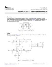
User's Guide
SBOU035A – July 2005 – Revised February 2006
DEM-OTA-SO-1A Demonstration Fixture
The DEM-OTA-SO-1A demonstration fixture is a generic, unpopulated printed circuit board (PCB) for
single operational transconductance amplifiers in SO-8 packages. Figure 1 shows the package pinout for
this PCB. For more information on these op amps, as well as good PCB layout techniques, see the
individual amplifier data sheets.
Figure 1. SO Package Pinout, Top View
The circuit schematic in Figure 2 shows the connections for all possible components. Each configuration
uses only some of the components.
Figure 2. Schematic for DEM-OTA-SO-1A
SBOU035A – July 2005 – Revised February 2006 DEM-OTA-SO-1A Demonstration Fixture 1
Submit Documentation Feedback
Verzeichnis
- ・ Blockdiagramm on Seite 1
- ・ Anwendungsbereich on Seite 6