
herunterladen
www.onsemi.com
EVAL BOARD USER’S MANUAL
© Semiconductor Components Industries, LLC, 2017
March, 2017 − Rev. 0
1 Publication Order Number:
EVBUM2497/D
EVBUM2497/D
IoT Development Kit (IDK)
Quick Start Guide
Getting Started with the IoT Development
Kit from ON Semiconductor
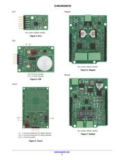
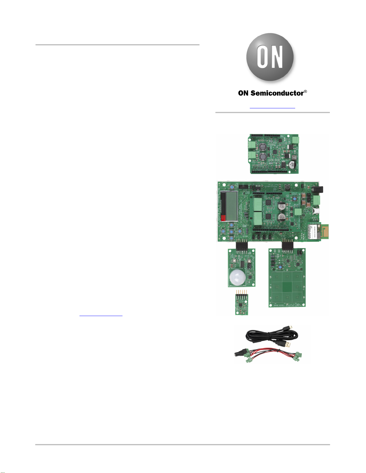
Available Shields
• IDK Baseboard
• Ambient Light Sensor (ALS) Shield
• Touch Shield, PIR Shield, Stepper Motor Shield
• LED Ballast Shield, Wi-Fi
®
Module
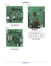
• BLDC Shield, PoE Shield, CAN Shield
Accessories
• Mini-USB Cable
• Cable Assembly
Tools Needed
• IDE Installer
• PC: Windows
®
PC with minimum 1 USB port, JRE/JDK version
8u101 or later installed. OS: Windows 7, 8 or 10.
Introduction
The IDK baseboard can be connected with different shields
depending on the required IoT application. The IDK baseboard allows
the user to create many types of IoT nodes and/or gateways depending
on which shields are used with the baseboard. The IDK baseboard is
configured by connecting the baseboard with the PC and USB cable
and using accompanying PC software.
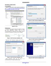
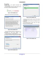
Software Installation
Programing/configuring the IDK requires the ON Semiconductor
IDE software. The IDE should be installed on the PC before
connecting the hardware to the PC. The Software Suite can be
downloaded from www.onsemi.com.
Steps for installation of the IDE are mentioned on page 5 of this
Quick Start guide.
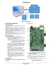
Hardware Setup
After the IDE software is installed, hardware can be connected as
shown in Figure 1. A single 12 V, 2 A power supply adapter powers
the evaluation board (e.g. CUI INC, model SMI24−12....12 V/2 A or
any other supporting V
OUT
= 10−35 V). Jumper settings required for
the correct operation of the baseboard and the shields are listed in
subsequent sections in this document. The shield boards plug directly
into the IDK baseboard. The PC connects to the IDK baseboard
through a USB cable.
The shields are classified into two broad categories − PMOD &
Arduino − based on the interface where the shields are connected to
the baseboard. In addition, Arduino-type shields include “Powered”
and “Non-Input Power” shields.
Verzeichnis