
herunterladen

User's Guide
SLOU274A–November 2009–Revised May 2010
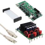
TAS5631DKD2EVM
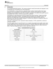
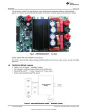
This user’s guide describes the operation of the evaluation module for the TAS5631 Digital Amplifier
Power Output Stage using TAS5518 Digital Audio PWM Processor from Texas Instruments. The user’s
guide also provides measurement data and design information like schematic, BOM, and PCB layout.
Contents
1 Introduction .................................................................................................................. 3
1.1 TAS5631DKD2EVM Features .................................................................................... 4
1.2 PCB Key map ...................................................................................................... 5
2 Quick Setup Guide .......................................................................................................... 5
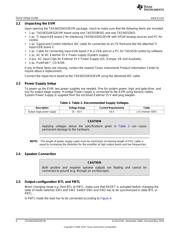
2.1 Electrostatic Discharge Warning ................................................................................. 5
2.2 Unpacking the EVM ................................................................................................ 6
2.3 Power Supply Setup ............................................................................................... 6
2.4 Speaker Connection ............................................................................................... 6
2.5 Output configuration BTL and PBTL ............................................................................ 6
2.6 GUI Software Installation .......................................................................................... 7
3 Protection .................................................................................................................... 8
3.1 Short Circuit Protection and Fault Reporting Circuitry ........................................................ 8
3.2 Fault Reporting ..................................................................................................... 8
4 TAS5631DKD2EVM Performance ........................................................................................ 9
4.1 THD+N vs. Power ................................................................................................ 11
4.2 THD+N vs. Frequency ........................................................................................... 12
4.3 FFT Spectrum ..................................................................................................... 13
4.4 Idle Noise FFT Spectrum ........................................................................................ 14
4.5 Channel Separation .............................................................................................. 15
4.6 Frequency Response ............................................................................................ 16
4.7 High Current Protection .......................................................................................... 17
4.8 Pop/Click ........................................................................................................... 18
4.9 Output Stage Efficiency .......................................................................................... 19
5 Related Documentation from Texas Instruments ..................................................................... 20
5.1 Additional Documentation ....................................................................................... 20
Appendix A Design Documents ............................................................................................... 20
List of Figures
1 TAS5631DKD2EVM – Top View.......................................................................................... 4
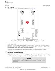
2 Integrated PurePath Digital™ Amplifier System ........................................................................ 4
3 Physical Structure for the TAS5631DKD2EVM (Approximate Layout) .............................................. 5
4 PBTL Mode Configuration ................................................................................................. 7
5 TAS5518 GUI Window ..................................................................................................... 8
6 THD+N vs. Power (BTL – 4 Ω) .......................................................................................... 11
7 THD+N vs. Power (BTL – 8 Ω) .......................................................................................... 11
8 THD+N vs. Power (PBTL – 2 Ω) ........................................................................................ 12
9 THD+N vs. Frequency (BTL – 4 Ω)..................................................................................... 12
10 THD+N vs. Frequency (BTL – 8 Ω)..................................................................................... 13
PurePath, Equibit are trademarks of Texas Instruments.
I
2
C is a trademark of NXP B.V. Corp Netherlands.
1
SLOU274A–November 2009–Revised May 2010 TAS5631DKD2EVM
Copyright © 2009–2010, Texas Instruments Incorporated
Verzeichnis
- ・ Blockdiagramm on Seite 20 Seite 21 Seite 23
- ・ Technische Daten on Seite 10
- ・ Anwendungsbereich on Seite 37