
herunterladen
2007-2011 Microchip Technology Inc. DS22035D-page 1
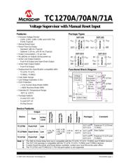
TC1270A/70AN/71A
Features:
• Precision Voltage Monitor
- 2.63V, 2.93V, 3.08V, 4.38V and 4.63V Trip
Points (Typical)
• Manual Reset Input
• Reset Time-Out Delay:
- Standard: 280 ms (Typical)
- Optional: 2.19 ms, and 35 ms (Typical)
• Power Consumption 15 µA max
• No glitches on outputs during power-up
• Active Low Output Options:
- Push-Pull Output and Open-Drain Output
• Active High Output Option:
- Push-Pull Output
• Replacement for (Specification compatible with):
- TC1270, TC1271
- TCM811, TCM812
• Fully Static Design
• Low-Voltage Operation (1.0V)
• ESD Protection:
- 4 kV Human Body Model (HBM)
- 400V Machine Model (MM)
• Extended (E) Temperature Range:
-40°C to +125°C
• Package Options:
- 4-Lead SOT-143
- 5-Lead SOT-23
- Pb-free Device
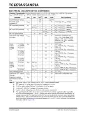
Package Types
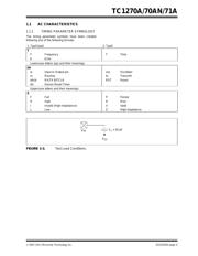
Functional Block Diagram
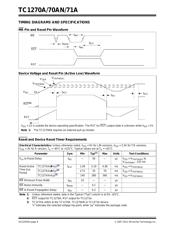
Device Features
1
2
4
3
TC1271A
SOT-143
V
SS
V
DD
RST
MR
1
2
4
3
TC1270A
TC1270AN
SOT-143
V
SS
V
DD
RST
MR
1
2
3
5
4
TC1271A
SOT-23-5
1
2
3
5
4
SOT-23-5
NC
NC
V
DD
MR
RST
V
SS
V
SS
V
DD
MR
RST
TC1270A
TC1270AN
18.5 k
V
DD
MR
RST
RST
Glitch Filter
Voltage
Detector
PP
PP
Output
Driver
Circuitry
(TC1271A)
(TC1270A)
Reset
Generator
and Delay
Timer
(2.19 ms,
35 ms,
280 ms)
OD
RST
(TC1270AN)
Device
Output
Reset Delay
(ms) (Typ)
(3)
Reset Trip
Point (V)
(3)
Voltage
Range (V)
Temperature
Range
Packages Comment
Type
Active
Level
TC1270A Push-Pull Low
2.19, 35,
280
(1)
4.63, 4.38,
3.08, 2.93,
2.63
(4)
1.0V to
5.5V
-40°C to
+125°C
SOT-143
(2)
,
SOT-23-5
Replaces TC1270 and
TCM811
TC1270AN Open-Drain Low
SOT-143
(2)
,
SOT-23-5
New Option
TC1271A Push-Pull High
SOT-143
(2)
,
SOT-23-5
Replaces TC1271 and
TCM812
Note 1: The 280 ms Reset delay time-out is compatible with the TC1270, TC1271, TCM811 and TCM812 devices.
2: The SOT-143 package is compatible with the TC1270, TC1271, TCM811 and TCM812 devices.
3: Custom Reset trip points and Reset delays available, contact your local Microchip sales office.
4: The TC1270/1 and TCM811/12 1.75V trip point option is not supported.
Voltage Supervisor with Manual Reset Input
Verzeichnis
- ・ Konfiguration des Pinbelegungsdiagramms on Seite 17 Seite 18
- ・ Teilenummerierungssystem on Seite 31
- ・ Markierungsinformationen on Seite 35
- ・ Blockdiagramm on Seite 1 Seite 19 Seite 20
- ・ Typisches Anwendungsschaltbild on Seite 25
- ・ Beschreibung der Funktionen on Seite 19
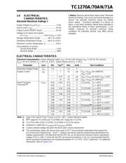
- ・ Technische Daten on Seite 6 Seite 7 Seite 40 Seite 41
- ・ Anwendungsbereich on Seite 25
- ・ Elektrische Spezifikation on Seite 4 Seite 6 Seite 7