
herunterladen

Application Report
SLAA063A - July 2002
1
Using References to Generate Offsets for the TLC55XX
Family Data Converter
Robert McCarthy Mixed Signal Products
ABSTRACT
This application report describes the process for using references to generate offsets for
Texas Instrument’s TLC55XX family data converters.
Contents
Description 1. . . . . . . . . . . . . . . . . . . . . . . . . . . . . . . . . . . . . . . . . . . . . . . . . . . . . . . . . . . . . . . . . . . . . . . . . . . . . .
High-Speed Converters 1. . . . . . . . . . . . . . . . . . . . . . . . . . . . . . . . . . . . . . . . . . . . . . . . . . . . . . . . . . . . . . . . . . . .
Biasing Techniques for a Split Supply 2. . . . . . . . . . . . . . . . . . . . . . . . . . . . . . . . . . . . . . . . . . . . . . . . . . . . . . . .
Biasing Techniques for a Single Supply 3. . . . . . . . . . . . . . . . . . . . . . . . . . . . . . . . . . . . . . . . . . . . . . . . . . . . . .
180 Degree Phase Shift 4. . . . . . . . . . . . . . . . . . . . . . . . . . . . . . . . . . . . . . . . . . . . . . . . . . . . . . . . . . . . . . . . . . . .
Power Supply and Layout Consideration 5. . . . . . . . . . . . . . . . . . . . . . . . . . . . . . . . . . . . . . . . . . . . . . . . . . . . .
List of Figures
1 High-Speed Converter Basic Circuit 2. . . . . . . . . . . . . . . . . . . . . . . . . . . . . . . . . . . . . . . . . . . . . . . . . . . . . . .
2 Example With Split Supply 3. . . . . . . . . . . . . . . . . . . . . . . . . . . . . . . . . . . . . . . . . . . . . . . . . . . . . . . . . . . . . . .
3 Example With Single Supply 3. . . . . . . . . . . . . . . . . . . . . . . . . . . . . . . . . . . . . . . . . . . . . . . . . . . . . . . . . . . . . .
4 Circuit With a 180 Degree Phase Shift 4. . . . . . . . . . . . . . . . . . . . . . . . . . . . . . . . . . . . . . . . . . . . . . . . . . . . .
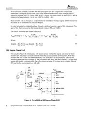
Description
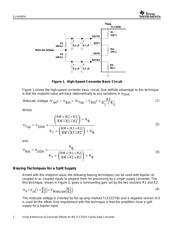
One common problem when interfacing to modern single supply A/D converters is biasing the
analog input so that it is centered within the reference voltage range of the A/D. For the more
common SAR type data converters it is often sufficient to set Vref top to V
CC
and Vref bottom to
GND. Then, biasing the midscale voltage of the input stage is simply a matter of generating
1/2V
CC
. This can be accomplished with a resistor divider network or, if more line/load stability is
needed, by using the TLE2425 virtual ground or the TLE2426 rail splitter.
High-Speed Converters
Some high-speed converters such as the TLC5510, TLC5540, and TLV5580 have internal
resistors that can be used to set internal reference voltages. On these devices, reference top
(REFT) and reference bottom (REFB) pins are available. Normally, these pins would be used as
reference inputs when an external reference is used. In this case we are relying on V
DDA
and
the internal divider to generate the reference voltages and take advantage of their availability. In
Figure 1, the two 100 KΩ (R1, R2) resistors from REFT to REFB divide this voltage in half,
generating a midpoint value between the top and bottom references. The small loading effect of
these resistors only slightly moves the references and these can be taken into account in the
DSP or other processor. The values shown for the internal reference divider resistors are the
nominal values from the data sheet. Keep in mind that only the ratio of these internal resistors is
accurate. The actual value of these internal resistors can vary by as much as 20%.