


herunterladen
User's Guide
SBAU169–April 2010
TMP512/TMP513EVM
This user’s guide describes the characteristics, operation, and the use of the TMP513 evaluation module
(EVM). It discusses the processes and procedures required to properly use this EVM board. This EVM is
designed to evaluate the performance of the TMP512 and TMP513 temperature sensors in a variety of
configurations. This document also includes a schematic and a complete bill of materials.
Contents
1 Overview ..................................................................................................................... 2
2 System Setup ................................................................................................................ 4
3 TMP513EVM Hardware Setup ........................................................................................... 10
4 TMP513 Software Overview ............................................................................................. 19
5 Bill of Materials ............................................................................................................. 25
List of Figures
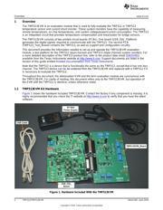
1 Hardware Included With the TMP513EVM .............................................................................. 2
2 Hardware Setup for the TMP513EVM.................................................................................... 4
3 Block Diagram of TMP513_Test_Board ................................................................................. 4
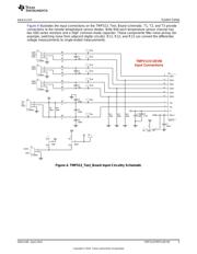
4 TMP513_Test_Board Input Circuitry Schematic........................................................................ 5
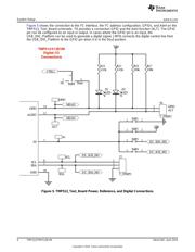
5 TMP513_Test_Board Power, Reference, and Digital Connections .................................................. 6
6 TMP513_Test_Board Connections to USB_DIG_Platform and EEPROM Schematic............................. 7
7 Theory of Operation For the USB_DIG_Platform ..................................................................... 10
8 Typical Hardware Connections .......................................................................................... 11
9 Connecting the Two Halves of the EVM................................................................................ 12
10 Connecting Power to the EVM........................................................................................... 13
11 Connecting the USB Cable............................................................................................... 14
12 Default Jumper Settings (TMP513_Test_Board)...................................................................... 15
13 Default Jumper Settings (USB_DIG_Platform) ........................................................................ 16
14 Block Diagram Tab........................................................................................................ 20
15 Registers Tab .............................................................................................................. 21
16 Calibrate Tab............................................................................................................... 22
17 Temperature Graph Tab.................................................................................................. 23
18 Shunt Graph Tab .......................................................................................................... 24
Microsoft, Windows are registered trademarks of Microsoft Corporation.
I
2
C is a trademark of NXP Semiconductors.
All other trademarks are the property of their respective owners.
1
SBAU169–April 2010 TMP512/TMP513EVM
Copyright © 2010, Texas Instruments Incorporated
Verzeichnis