
herunterladen

TMS320C6424
www.ti.com
SPRS347D–MARCH 2007–REVISED DECEMBER 2009
TMS320C6424 Fixed-Point Digital Signal Processor
Check for Samples: TMS320C6424
1 TMS320C6424 Fixed-Point Digital Signal Processor
1.1 Features
1
• High-Performance Digital Signal Processor • C64x+ L1/L2 Memory Architecture
(C6424)
– 256K-Bit (32K-Byte) L1P Program
– 2.5-, 2-, 1.67-, 1.43-ns Instruction Cycle Time RAM/Cache [Flexible Allocation]
– 400-, 500-, 600-, 700-MHz C64x+™ Clock Rate – 640K-Bit (80K-Byte) L1D Data RAM/Cache
[Flexible Allocation]
– Eight 32-Bit C64x+ Instructions/Cycle
– 1M-Bit (128K-Byte) L2 Unified Mapped
– 3200, 4000, 4800, 5600 MIPS
RAM/Cache [Flexible Allocation]
– Fully Software-Compatible With C64x
• Endianess: Supports Both Little Endian and
– Commercial and Automotive (Q or S suffix)
Big Endian
Grades
• External Memory Interfaces (EMIFs)
– Low-Power Device (L suffix)
– 32-Bit DDR2 SDRAM Memory Controller With
• VelociTI.2™ Extensions to VelociTI™
256M-Byte Address Space (1.8-V I/O)
Advanced Very-Long-Instruction-Word (VLIW)
• Supports up to 333-MHz (data rate) bus
TMS320C64x+™ DSP Core
and interfaces to DDR2-400 SDRAM
– Eight Highly Independent Functional Units
– Asynchronous 16-Bit Wide EMIF (EMIFA)
With VelociTI.2 Extensions:
With up to 128M-Byte Address Reach
• Six ALUs (32-/40-Bit), Each Supports
• Flash Memory Interfaces
Single 32-Bit, Dual 16-Bit, or Quad 8-Bit
Arithmetic per Clock Cycle – NOR (8-/16-Bit-Wide Data)
• Two Multipliers Support Four 16 x 16-Bit – NAND (8-/16-Bit-Wide Data)
Multiplies (32-Bit Results) per Clock
• Enhanced Direct-Memory-Access (EDMA)
Cycle or Eight 8 x 8-Bit Multiplies (16-Bit
Controller (64 Independent Channels)
Results) per Clock Cycle
• Two 64-Bit General-Purpose Timers (Each
– Load-Store Architecture With Non-Aligned
Configurable as Two 32-Bit Timers)
Support
• One 64-Bit Watch Dog Timer
– 64 32-Bit General-Purpose Registers
• Two UARTs (One with RTS and CTS Flow
– Instruction Packing Reduces Code Size
Control)
– All Instructions Conditional
• Master/Slave Inter-Integrated Circuit (I
2
C Bus™)
– Additional C64x+™ Enhancements
• Two Multichannel Buffered Serial Ports
• Protected Mode Operation (McBSPs)
• Exceptions Support for Error Detection – I2S and TDM
and Program Redirection
– AC97 Audio Codec Interface
• Hardware Support for Modulo Loop
– SPI
Auto-Focus Module Operation
– Standard Voice Codec Interface (AIC12)
• C64x+ Instruction Set Features
– Telecom Interfaces – ST-Bus, H-100
– Byte-Addressable (8-/16-/32-/64-Bit Data)
– 128 Channel Mode
– 8-Bit Overflow Protection
• Multichannel Audio Serial Port (McASP0)
– Bit-Field Extract, Set, Clear
– Four Serializers and SPDIF (DIT) Mode
– Normalization, Saturation, Bit-Counting
• 16-Bit Host-Port Interface (HPI)
– VelociTI.2 Increased Orthogonality
• 32-Bit 33-MHz, 3.3-V Peripheral Component
– C64x+ Extensions
Interconnect (PCI) Master/Slave Interface
• Compact 16-bit Instructions
• Additional Instructions to Support
Complex Multiplies
1
Please be aware that an important notice concerning availability, standard warranty, and use in critical applications of Texas
Instruments semiconductor products and disclaimers thereto appears at the end of this data sheet.
PRODUCTION DATA information is current as of publication date.
Copyright © 2007–2009, Texas Instruments Incorporated
Products conform to specifications per the terms of the Texas
Instruments standard warranty. Production processing does not
necessarily include testing of all parameters.
Verzeichnis
- ・ Konfiguration des Pinbelegungsdiagramms on Seite 21 Seite 35 Seite 40 Seite 52 Seite 68
- ・ Abmessungen des Paketumrisses on Seite 242 Seite 243 Seite 244 Seite 245
- ・ Markierungsinformationen on Seite 242 Seite 243 Seite 244 Seite 245 Seite 246
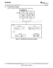
- ・ Blockdiagramm on Seite 4 Seite 9 Seite 123 Seite 124 Seite 134
- ・ Technische Daten on Seite 125 Seite 127 Seite 129 Seite 130 Seite 131
- ・ Anwendungsbereich on Seite 2 Seite 126
- ・ Elektrische Spezifikation on Seite 122 Seite 127 Seite 128 Seite 129 Seite 130