
herunterladen
1 Introduction
1.1 Description
User's Guide
SLOU184 – July 2006
TPA5051EVM
Contents
1 Introduction .......................................................................................... 1
2 Software ............................................................................................. 2
3 Operation ............................................................................................ 6
4 Reference ............................................................................................ 9
5 TPA5051EVM Schematic Diagram ............................................................. 12
List of Figures
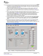
1 TPA5051 in I
2
S Mode With Separate Delays for Left and Right Channels ................. 3
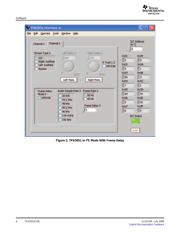
2 TPA5051 in I
2
S Mode With Frame Delay........................................................ 4
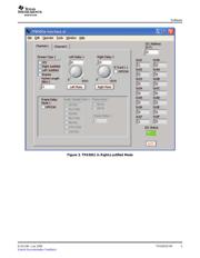
3 TPA5051 in Right-Justified Mode ................................................................ 5
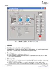
4 TPA5051 in I
2
S Mode – Unable to Communicate .............................................. 6
5 Top Layer of the TPA5051EVM .................................................................. 7
6 Bottom Layer of the TPA5051EVM .............................................................. 8
7 TPA5051EVM Top Layer .......................................................................... 9
8 TPA5051EVM Second Layer ..................................................................... 9
9 TPA5051EVM Third Layer ....................................................................... 10
10 TPA5051EVM Bottom Layer ..................................................................... 10
List of Tables
1 Bill of Materials .................................................................................... 11
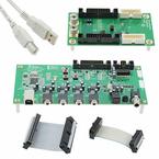
The TPA5051 evaluation module (EVM) consists of a single TPA5051 audio delay device, along with other
external components mounted on a printed-circuit board (PCB) that can be used to independently delay
two digital audio streams. Each digital audio stream consists of a left and right channel, both of which can
be delayed up to 4095 samples (with a 48-kHz sampling rate, that equates to more than 85ms of delay).
The TPA5051EVM is designed to work seamlessly with the TI Input USB board, but can function as a
stand-alone board for pass-through testing in any system. All that is required is an I
2
S audio source, an
I
2
C controller, and a 5-V supply.
The TPA5051EVM also includes an onboard digital-to-analog controller (DAC), the PCM1606, which can
convert I
2
S or left-justified data to an analog out. The analog out is filtered on the board and can be
viewed with a scope probe.
National Instruments is a trademark of National Instruments Corporation.
SLOU184 – July 2006 TPA5051EVM 1
Submit Documentation Feedback