

herunterladen

User's Guide
SLUU274 – May 2007
Using the TPS40193EVM-001
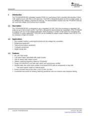
The TPS40193EVM-001 evaluation module is a 12V to 1.8V synchronous buck
converter built around the TPS40193 synchronous buck controller. This module
provides a convenient test platform for both evaluating the TPS40193 controller in a
real application and prototyping synchronous buck converters using the TPS40193
controller.
Contents
1 Introduction .......................................................................................... 2
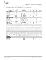
2 TPS40193EVM-001 Electrical Performance Specifications ................................... 3
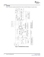
3 Schematic ........................................................................................... 4
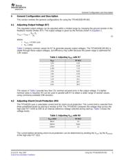
4 General Configuration and Description .......................................................... 5
5 Test Setup ........................................................................................... 8
6 TPS40193EVM-001 Typical Performance Data and Characteristic Curves............... 11
7 EVM Assembly Drawings and Layout .......................................................... 14
8 Bill of Materials .................................................................................... 18
List of Figures
1 TPS40193EVM-001 Schematic ................................................................... 4
2 TPS40193EVM-001 Recommended Test Setup ............................................... 9
3 TPS40193EVM-001 Output Ripple Measurement—Tip and Barrel Using TP15 and
TP16 .................................................................................................. 9
4 TPS40193EVM-001 Control Loop Measurement Setup ..................................... 10
5 TPS40193EVM-001 Efficiency vs Load Current .............................................. 11
6 TPS40193EVM-001 Output Voltage vs Load Current ( ± 0.5% Window Shown) .......... 12
7 TPS40193EVM-001 Output Voltage Ripple ................................................... 12
8 TPS40193EVM-001 Switching Waveforms (V
IN
= 8V, I
OUT
= 10A) ......................... 13
9 TPS40193EVM-001 Switching Waveforms (V
IN
= 14V, I
OUT
= 10A) ....................... 13
10 TPS40193EVM-001 Gain and Phase vs Frequency ......................................... 14
11 TPS40193EVM-001 Gain and Phase vs Frequency ......................................... 14
12 TPS40193EVM-001 Component Placement .................................................. 15
13 TPS40193EVM-001 Silkscreen ................................................................. 15
14 TPS40193EVM-001 Top Copper Layer ........................................................ 16
15 TPS40193EVM-001 Bottom Copper Layer ................................................... 16
16 TPS40193EVM-001 Internal Layer 1 ........................................................... 17
17 TPS40193EVM-001 Internal Layer 2 ........................................................... 17
List of Tables
1 TPS40193EVM-001 Electrical and Performance Specifications ............................. 3
2 Adjusting V
OUT
with R7 ............................................................................. 5
3 Adjusting V
SCP
with R9 ............................................................................. 5
4 Test Point Descriptions ............................................................................ 6
5 Bill of Materials .................................................................................... 18
SLUU274 – May 2007 Using the TPS40193EVM-001 1
Submit Documentation Feedback
Verzeichnis