
herunterladen
User's Guide
SLVU353–November 2009
TPS54326EVM-540 3-A, SWIFT
TM
Regulator Evaluation
Module
Contents
1 Introduction .................................................................................................................. 2
1.1 Background ......................................................................................................... 2
1.2 Performance Specification Summary ............................................................................ 2
1.3 Modifications ........................................................................................................ 3
2 Test Setup and Results .................................................................................................... 3
2.1 Input / Output Connections ....................................................................................... 3
2.2 Start Up Procedure ................................................................................................ 4
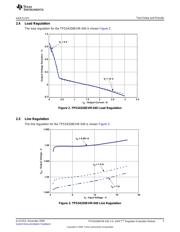
2.3 Efficiency ............................................................................................................ 4
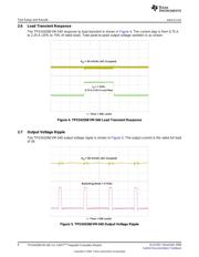
2.4 Load Regulation .................................................................................................... 5
2.5 Line Regulation ..................................................................................................... 5
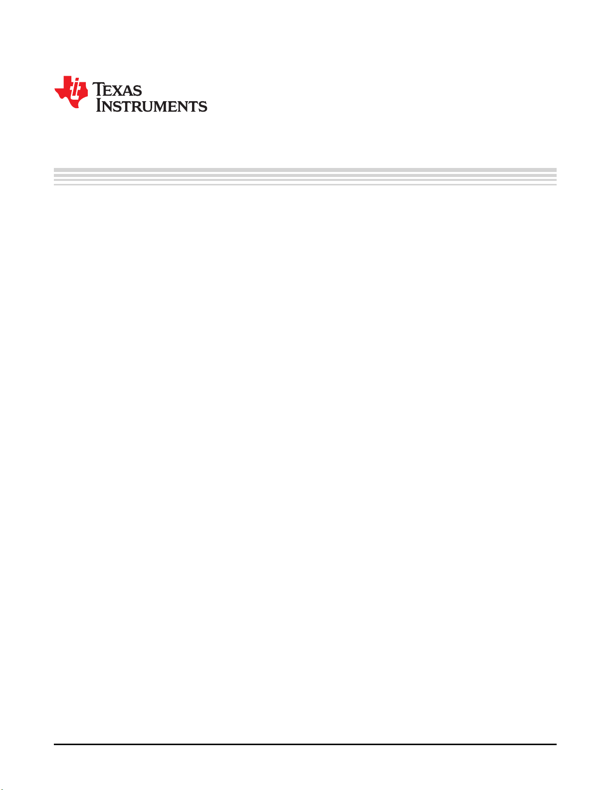
2.6 Load Transient Response ........................................................................................ 6
2.7 Output Voltage Ripple ............................................................................................. 6
2.8 Input Voltage Ripple ............................................................................................... 7
2.9 Start Up .............................................................................................................. 7
2.10 Switching Frequency .............................................................................................. 8
3 Board Layout ................................................................................................................ 8
3.1 Layout ............................................................................................................... 8
4 Schematic, Bill of Materials and Reference ............................................................................ 12
4.1 Schematic ......................................................................................................... 12
4.2 Bill of Materials .................................................................................................... 13
4.3 Reference .......................................................................................................... 13
List of Figures
1 TPS54326EVM-540 Efficiency ............................................................................................ 4
2 TPS54326EVM-540 Load Regulation.................................................................................... 5
3 TPS54326EVM-540 Line Regulation..................................................................................... 5
4 TPS54326EVM-540 Load Transient Response......................................................................... 6
5 TPS54326EVM-540 Output Voltage Ripple ............................................................................. 6
6 TPS54326EVM-540 Input Voltage Ripple ............................................................................... 7
7 TPS54326EVM-540 Start Up.............................................................................................. 7
8 TPS54326-540 Switching Frequency .................................................................................... 8
9 Top Assembly ............................................................................................................... 9
10 Top Layer................................................................................................................... 10
11 Internal Layer 1............................................................................................................ 10
12 Internal Layer 2............................................................................................................ 11
13 Bottom Layer............................................................................................................... 11
14 Bottom Assembly.......................................................................................................... 11
15 TPS54326EVM-540 Schematic Diagram............................................................................... 12
List of Tables
D-CAP2 is a trademark of Texas Instruments.
1
SLVU353–November 2009
TPS54326EVM-540 3-A, SWIFT
TM
Regulator Evaluation Module
Submit Documentation Feedback
Copyright © 2009, Texas Instruments Incorporated