

herunterladen

User's Guide
SLVU223B–February 2008– Revised May 2011
TPS61181EVM-259 / TPS61182EVM-259
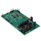
This user's guide describes the characteristics, operation, and use of the TPS6118xEVM-259 evaluation
module (EVM). This EVM contains either Texas Instruments' TPS61181 (-001 build) or TPS61182 (-002
build) or TPS61181A (-003 build)-based WLED power solutions, each of which provides up to six
independently regulated current outputs using a single inductor step-up (boost) converter. The current
outputs are ideal for driving a WLED backlight in notebook/laptop computers. A separate EVM,
WLEDEVM-260, contains eight strings of 10 series WLEDs and connects to the TPS6118x EVMs via a
14-pin ribbon cable to simplify evaluation. This user's guide includes EVM specifications, recommended
test setup, test results, bill of materials, and a schematic diagram for the TPS61181/2/1AEVM.
Contents
1 Introduction .................................................................................................................. 2
2 Input/Output Connector Descriptions ..................................................................................... 3
3 Board Layout ................................................................................................................ 7
4 Schematic and Bill of Materials ........................................................................................... 9
List of Figures
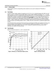
1 Efficiency vs Total WLED Output Current .............................................................................. 4
2 Dimming Linearity........................................................................................................... 4
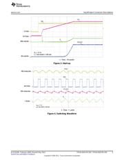
3 Start-up....................................................................................................................... 5
4 Switching Waveform........................................................................................................ 5
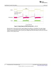
5 Output Ripple at PWM Dimming with C
O
= 4.7 μF...................................................................... 6
6 Top Assembly Layer........................................................................................................ 7
7 Top Layer .................................................................................................................... 7
8 Bottom Layer ................................................................................................................ 8
9 HPA259A Schematic ....................................................................................................... 9
List of Tables
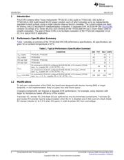
1 Typical Performance Specification Summary ........................................................................... 2
2 HPA259 Bill of Materials.................................................................................................. 10
1
SLVU223B–February 2008–Revised May 2011 TPS61181EVM-259 / TPS61182EVM-259
Submit Documentation Feedback
Copyright © 2008–2011, Texas Instruments Incorporated
Verzeichnis
- ・ Blockdiagramm on Seite 9 Seite 10 Seite 11
- ・ Technische Daten on Seite 2
- ・ Anwendungsbereich on Seite 13