


herunterladen

User's Guide
SLVUAC4–October 2014
TPS65400 4.5- to 18-V Input Flexible Power Management
Unit with PMBus/I
2
C Interface Evaluation Module
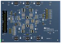
This document presents the information required to operate the TPS65400 PMIC as well as the support
documentation including schematic, layout, hardware setup and bill of materials.
Contents
1 Background................................................................................................................... 2
2 TPS65400 EVM Schematic ................................................................................................ 3
3 Board Layout ................................................................................................................. 4
4 Bench Test Setup Conditions .............................................................................................. 7
4.1 Headers Description and Jumper Placement ................................................................... 7
4.2 Hardware Requirement ............................................................................................ 8
4.3 Hardware Setup..................................................................................................... 8
4.4 Software Install...................................................................................................... 9
4.5 Software Operation ............................................................................................... 10
5 Power-Up Procedure....................................................................................................... 13
6 Power-Down Procedure ................................................................................................... 13
7 Bill of Materials ............................................................................................................. 14
List of Figures
1 TPS65400 EVM Schematic ................................................................................................ 3
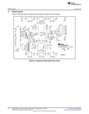
2 Component Placement (Top Layer)....................................................................................... 4
3 Board Layout (Top Layer) .................................................................................................. 5
4 Board Layout (Second Layer).............................................................................................. 5
5 Board Layout (Third Layer)................................................................................................. 6
6 Board Layout (Bottom Layer) .............................................................................................. 6
7 Headers Description and Jumper Placement ............................................................................ 7
8 USB Interface Adapter Quick Connection Diagram..................................................................... 9
9 Connect to TPS65400 EVM with EVM GUI............................................................................. 10
10 Go to Main Setting Panel.................................................................................................. 10
11 Global Commands ......................................................................................................... 11
12 Status and Main Setting Panel ........................................................................................... 11
13 Phase Shift Panel .......................................................................................................... 12
14 Power Sequence Panel ................................................................................................... 12
15 Vref Ramping Up and Down Panel ...................................................................................... 13
List of Tables
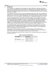
1 Summary of Performance .................................................................................................. 2
2 Input/Output Connection.................................................................................................... 8
3 Jumpers....................................................................................................................... 8
4 Bill of Materials ............................................................................................................. 14
Microsoft, Windows, Internet Explorer are registered trademarks of Microsoft Corporation.
VeriSign is a registered trademark of VeriSign, Incorporated.
1
SLVUAC4–October 2014 TPS65400 4.5- to 18-V Input Flexible Power Management Unit with
PMBus/I
2
C Interface Evaluation Module
Submit Documentation Feedback
Copyright © 2014, Texas Instruments Incorporated