


herunterladen
1 Background
2 Setup
User's Guide
SBVU002A – September 2003 – Revised June 2005
DEM-SOT23LDO DEMONSTRATION FIXTURE
This User's Guide describes the characteristics, operation, and use of the
DEM-SOT23LDO demonstration module (DEM).
This DEM is designed to help the user easily evaluate and test the operation and functionality of Texas
Instruments 5 and 6 lead SOT23 (DBV) package LDOs. This User's Guide includes setup instructions, a
schematic diagram, and a PCB layout drawing for the DEM.
This DEM is specifically designed to be assembled with surface mount devices with footprints ranging
from 603 to 1210. Additional holes have also been provided to accommodate leaded components. Refer
to the product data sheet for specific guidelines when selecting components. For all designs, C1 and C2
are used as the input and output capacitors. Adjustable devices in the 5 lead packages use only R1 and
R2. Refer to the typical application circuits in the product data sheet when populating the components. J5
is used to provide access to pin 4 for LDOs that feature a power good (PG) pin. The specific IC to be
tested may be obtained through TI's sample program. All components other than the PWB are user
supplied.
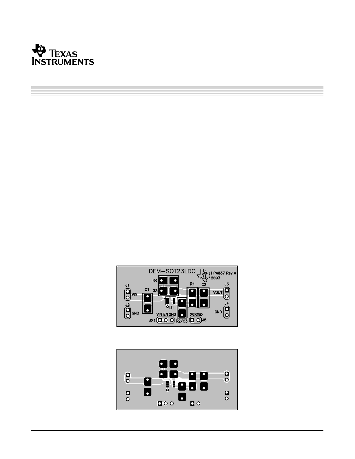
Figure 1 through Figure 3 show the board layout for the DEM-SOT23LDO printed circuit board.
Figure 1. Assembly Layer
Figure 2. Top Layer Routing
DEM-SOT23LDO DEMONSTRATION FIXTURESBVU002A – September 2003 – Revised June 2005 1
Verzeichnis
- ・ Blockdiagramm on Seite 2
- ・ Anwendungsbereich on Seite 3