

herunterladen
User's Guide
SLVU387–July 2010
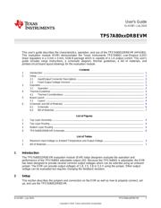
TPS7A80xxDRBEVM
This user’s guide describes the characteristics, operation, and use of the TPS7A8001DRBEVM (HPA562).
This evaluation module (EVM) demonstrates the Texas Instruments TPS7A8001 Low-Dropout (LDO)
linear regulators in a 3-mm x 3-mm, SON-8 package which is capable of a 1-A output current. This user’s
guide includes setup instructions, a schematic diagram, thermal guidelines, a bill of materials, and
printed-circuit board layout drawings for the evaluation module.
Contents
1 Introduction .................................................................................................................. 1
2 Setup ......................................................................................................................... 1
2.1 Input/Output Connector Descriptions ............................................................................ 2
2.2 Fixed Output Voltage Versions ................................................................................... 2
3 Operation ..................................................................................................................... 3
3.1 Operation ............................................................................................................ 3
4 Thermal Guidelines ......................................................................................................... 3
4.1 Thermal Considerations ........................................................................................... 3
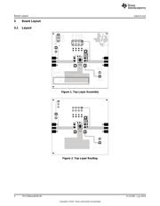
5 Board Layout ................................................................................................................ 4
5.1 Layout ............................................................................................................... 4
6 Schematic and Bill of Materials ........................................................................................... 6
6.1 Schematic ........................................................................................................... 6
6.2 Bill of Materials ..................................................................................................... 7
List of Figures
1 Top Layer Assembly........................................................................................................ 4
2 Top Layer Routing.......................................................................................................... 4
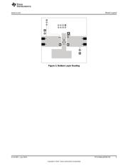
3 Bottom Layer Routing ...................................................................................................... 5
4 TPS7A8001DRBEVM Schematic......................................................................................... 6
List of Tables
1 Maximum Input Voltage vs Ambient Temperature and Output Voltage ............................................. 3
2 Bill of Materials.............................................................................................................. 7
1 Introduction
The TPS7A8001DRBEVM evaluation module (EVM) helps designers evaluate the operation and
performance of the TPS7A8001 adjustable output LDO. Because the TPS7A8001 is adjustable, the EVM
has been designed to provide several common output voltages which can be selected using an onboard
jumper. The EVM can provide output voltages of 1.8, 2.5, 2.8 or 3.3 V using the jumper. Other output
voltage can be evaluated but requires changing the feedback resistors.
2 Setup
This section describes the jumpers and connectors on the EVM as well as how to properly connect, set
up, and use the TPS7A8001DRBEVM.
1
SLVU387–July 2010 TPS7A80xxDRBEVM
Copyright © 2010, Texas Instruments Incorporated
Verzeichnis
- ・ Blockdiagramm on Seite 6 Seite 7
- ・ Anwendungsbereich on Seite 9