
herunterladen

User's Guide
SLAU546–March 2014
TRF37x73 and TRF37x75 EVM
This document outlines the basic steps and functions that are required to ensure the proper operation and
quick setup of the TRF37x73 and TRF37x75 EVM. This document also includes a schematic diagram, a
bill of materials (BOM), printed-circuit board (PCB) layouts, board loss plots, and test block diagrams.
Throughout this document, the abbreviations EVM, TRF37x73/75 EVM, and the term evaluation module
are synonymous with the TRF37x73 and TRF37x75 EVM, unless otherwise noted.
Contents
1 Contents ...................................................................................................................... 2
2 EVM Overview ............................................................................................................... 2
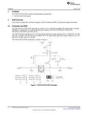
2.1 Schematic and BOM ............................................................................................... 2
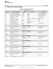
2.2 TRF37x73/75 EVM Bill of Material ............................................................................... 3
2.3 General Usage Information........................................................................................ 4
3 EVM Layout................................................................................................................... 4
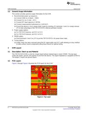
3.1 Description: Stack up and Material............................................................................... 4
3.2 PCB Layers.......................................................................................................... 4
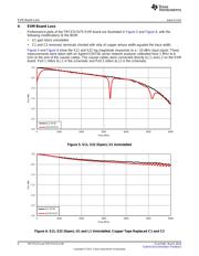
4 EVM Board Loss............................................................................................................. 6
5 Test Block Diagrams ........................................................................................................ 7
5.1 Noise Figure......................................................................................................... 7
5.2 Gain and P1dB...................................................................................................... 7
5.3 OIP3 .................................................................................................................. 8
List of Figures
1 TRF37x73/75 EVM Schematic............................................................................................. 2
2 Top Layer..................................................................................................................... 4
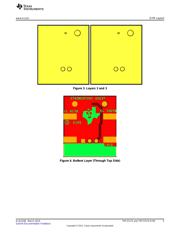
3 Layers 2 and 3 ............................................................................................................... 5
4 Bottom Layer (Through Top Side)......................................................................................... 5
5 S11, S22 (Open), U1 Uninstalled.......................................................................................... 6
6 S11, S22 (Open), U1 and L1 Uninstalled, Copper Tape Replaced C1 and C2 .................................... 6
List of Tables
1 TRF37x73/75 EVM BOM ................................................................................................... 3
1
SLAU546–March 2014 TRF37x73 and TRF37x75 EVM
Submit Documentation Feedback
Copyright © 2014, Texas Instruments Incorporated
Verzeichnis
- ・ Blockdiagramm on Seite 7 Seite 8
- ・ Anwendungsbereich on Seite 9 Seite 12