

herunterladen

User's Guide
SLUUB75–February 2015
Using the UCC28730EVM-552 10-W Adaptor Module With
PSR and Wake-Up Monitor
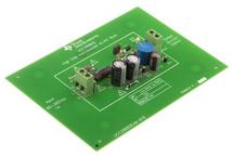
The UCC28730EVM-552 evaluation module is a 10-W off-line discontinuous mode (DCM) flyback
converter that provides constant-voltage (CV) and constant-current (CC) output regulation without the use
of an optical coupler. The controller uses primary-side regulation (PSR) and detects a wake-up signal from
the UCC24650 secondary-side voltage-droop monitor for improved transient response to large load steps.
The EVM demonstrates how the UCC28730 can provide ultra-low standby power without sacrificing start-
up time or output transient response with an internal 700-V start-up switch, dynamically controlled
operating states, and a tailored modulation profile. The UCC28730 uses frequency modulation, peak
primary current modulation, valley switching and valley skipping in its control algorithm in order to
maximize efficiency over the entire operating range.
Contents
1 Description.................................................................................................................... 2
1.1 Typical Applications ................................................................................................ 3
1.2 Features.............................................................................................................. 3
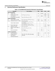
2 Electrical Performance Specifications..................................................................................... 4
3 Schematic..................................................................................................................... 5
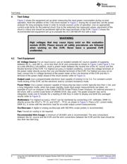
4 Test Setup .................................................................................................................... 6
4.1 Test Equipment ..................................................................................................... 6
4.2 Recommended Test Setup........................................................................................ 7
4.3 List of Test Points................................................................................................... 8
4.4 Applying Power to the EVM ....................................................................................... 9
4.5 No-Load Power Consumption..................................................................................... 9
4.6 Line/Load Regulation and Efficiency Measurement Procedure .............................................. 9
4.7 Output Voltage Ripple.............................................................................................. 9
4.8 Equipment Shutdown............................................................................................. 10
5 Performance Data and Typical Characteristic Curves................................................................. 10
5.1 Efficiency ........................................................................................................... 10
5.2 No-Load Power Consumption ................................................................................... 11
5.3 Output Voltage vs Output Current .............................................................................. 11
5.4 Transient Response............................................................................................... 12
5.5 Output Ripple ...................................................................................................... 13
5.6 Turn On Waveform................................................................................................ 14
5.7 Switching Waveform .............................................................................................. 15
5.8 EMI Dithering Waveform ......................................................................................... 16
5.9 ENS Function ...................................................................................................... 16
6 EVM Assembly Drawing and PCB Layout .............................................................................. 18
7 Bill of Materials ............................................................................................................. 20
List of Figures
1 UCC28730EVM-552 Schematic ........................................................................................... 5
2 UCC28730EVM-552 Recommended Test Set Up For No-Load Operation.......................................... 7
3 FUCC28730EVM-552 Recommended Test Set Up With Load........................................................ 8
4 UCC28730EVM-552 Average Efficiency................................................................................ 10
5 UCC28730EVM-552 Efficiency........................................................................................... 10
6 UCC28730EVM-552 No-Load Power Consumption................................................................... 11
1
SLUUB75–February 2015 Using the UCC28730EVM-552 10-W Adaptor Module With PSR and Wake-
Up Monitor
Submit Documentation Feedback
Copyright © 2015, Texas Instruments Incorporated