

herunterladen

Product
Folder
Order
Now
Technical
Documents
Tools &
Software
Support &
Community
An IMPORTANT NOTICE at the end of this data sheet addresses availability, warranty, changes, use in safety-critical applications,
intellectual property matters and other important disclaimers. PRODUCTION DATA.
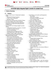
UCD3138A
SLUSC66E –MARCH 2015–REVISED FEBRUARY 2017
UCD3138A Highly-Integrated Digital Controller for Isolated Power
1 Device Overview
1
1.1 Features
1
• Digital Control of up to 3 Independent Feedback
Loops
– Dedicated PID-Based Hardware
– 2-Pole, 2-Zero Configurable
– Nonlinear Control
• Soft-Start and Soft-Stop with and without Prebias
• Fast Input Voltage Feed Forward Hardware
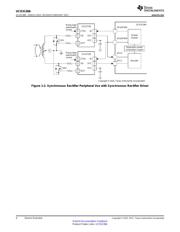
• Synchronous Rectifier Dead Time Optimization
Peripheral to Use with UCD7138 Synchronous
Rectifier Driver
• Up to 16 MHz Error Analog-to-Digital Converter
(EADC)
– Configurable Resolution as Small as 1 mV/LSB
– Automatic Resolution Selection
– Up to 8× Oversampling
– Hardware-Based Averaging (up to 8×)
– 10-Bit Effective DAC With 4 Bits of Dither
– Adaptive Sample Trigger Positioning
• Up to 8 High-Resolution Digital Pulse Width
Modulated (DPWM) Outputs
– 250-ps Pulse Width Resolution
– 4-ns Frequency and Phase Resolution
– Adjustable Phase-Shift Between Outputs
– Adjustable Dead-band Between Pairs
– Cycle-by-Cycle Duty Cycle Matching
– Up to 2-MHz Switching Frequency
• Configurable PWM Edge Movement
– Trailing Modulation
– Leading Modulation
– Triangular Modulation
• Configurable Feedback Control
– Voltage Mode
– Average Current Mode
– Peak Current Mode Control
– Constant Current
– Constant Power
• Configurable Modulation Methods
– Frequency Modulation
– Phase-Shift Modulation
– Pulse Width Modulation
• Fast, Automatic, and Smooth Mode Switching
– Frequency Modulation and PWM
– Phase-Shift Modulation and PWM
– Frequency Modulation and Phase-Shift
Modulation
• High Efficiency and Light Load Management
– Burst Mode
– Ideal Diode Emulation
– Synchronous Rectifier Soft On/Off
– Low IC Standby Power
• Primary Side Voltage Sensing
• Copper Trace Current Sensing
• Flux and Phase Current Balancing
• Current Share Bus Support
– Average or Master and Slave
• Feature Rich Fault Protection Options
– 7 High-Speed Analog Comparators
– Cycle-by-Cycle Current Limiting
– Programmable Fault
– External Fault Capability
– 10 Digital Comparators
– Programmable Blanking Time
• Synchronization of DPWM Waveforms Between
Multiple UCD3138A devices
• 14-Channel, 12-Bit, 267-ksps General-Purpose
ADC
– Programmable Averaging Filters
– Dual Sample and Hold
• Internal Temperature Sensor
• Fully Programmable High-Performance 31.25-
MHz, 32-Bit ARM7TDMI-S™ Processor
– 32 KB of Program Flash
– 2 KB of Data Flash with ECC
– 4 KB of Data RAM
– Firmware Boot-Load in the Field via PMBus or
UART
• Communication Peripherals
– PMBus
– 1 UART
• UART Auto-baud Rate Adjustment
• Timer Capture with Selectable Input Pins
• Up to 5 Additional General Purpose Timers
• Built In Watchdog: BOD and POR
• 64-Pin QFN and 40-Pin QFN Package
• Operating Temperature: –40°C to +125°C
• Debug Interface
– Code Composer Studio™ with JTAG Interface
– Fusion Digital Power™ Designer GUI Support
Verzeichnis
- ・ Konfiguration des Pinbelegungsdiagramms on Seite 8 Seite 9 Seite 10 Seite 11 Seite 12
- ・ Abmessungen des Paketumrisses on Seite 2 Seite 75 Seite 77 Seite 78 Seite 79
- ・ Paket-Footprint-Pad-Layout on Seite 80
- ・ Markierungsinformationen on Seite 75
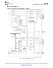
- ・ Blockdiagramm on Seite 3 Seite 45 Seite 46 Seite 47 Seite 60
- ・ Typisches Anwendungsschaltbild on Seite 58
- ・ Technische Daten on Seite 14 Seite 15 Seite 16 Seite 17 Seite 18
- ・ Anwendungsbereich on Seite 2 Seite 73 Seite 74
- ・ Elektrische Spezifikation on Seite 15 Seite 16 Seite 17 Seite 18