
1
REV. 1.0.0 XR16M890 EVALUATION BOARD USER’S MANUAL
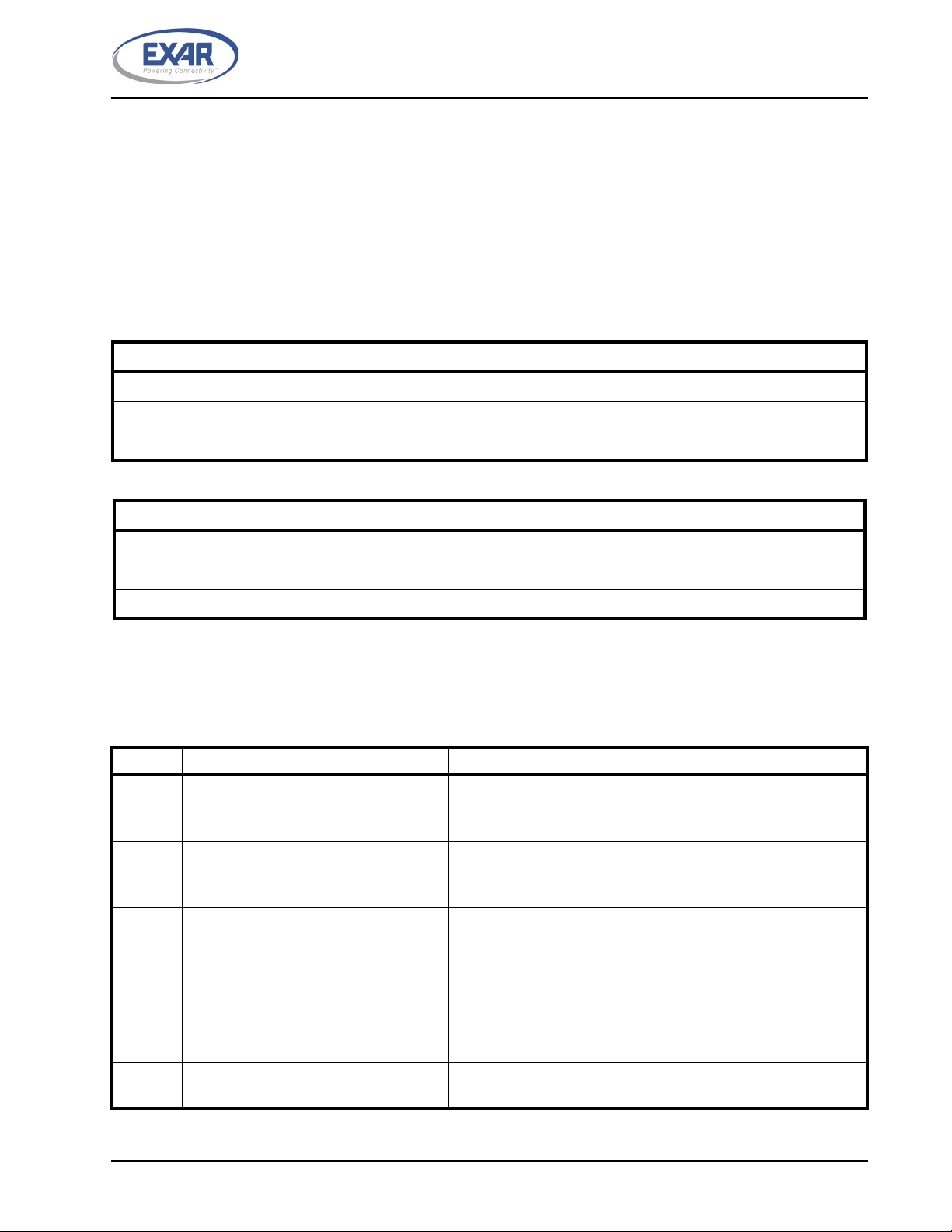
INTRODUCTION
This user’s manual is for the XR16M890 evaluation board. Table 1 shows the different devices and packages
that the evaluation board supports. This user’s manual will describe the hardware setup required to operate the
different packages.
1.0 HARDWARE SETUP
1.1 Packages description
The evaluation board supports all 3 packages of the XR16M890. The ordering part number, package and
location on the board is shown below in Table 1. Table 2 lists the evaluation board ordering part numbers.
TABLE 1: PACKAGE LIST
ORDERING PART NUMBER PACKAGE LOCATION
XR16M890IL32-F 32-pin QFN U7
XR16M890IL40-F 40-pin QFN U5
XR16M890IM48-F 48-pin TQFP U8
TABLE 2: EVALUATION BOARD ORDERING PART NUMBERS
PART NUMBER
XR16M890L32-0A-EB
XR16M890L40-0A-EB
XR16M890M48-0A-EB
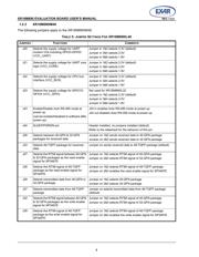
1.2 Jumper Settings
1.2.1 XR16M890IL32
The following jumpers apply to the XR16M890IL32:
TABLE 3: JUMPER SETTINGS FOR XR16M890IL32
JUMPERS FUNCTIONS COMMENTS
J20 Selects the supply voltage for UART
modem I/Os including GPIO3-GPIO0
(VCC_UART)
Jumper in 1&2 selects 3.3V (default)
Jumper in 3&4 selects 2.5V
Jumper in 5&6 selects 1.8V
J21 Selects the supply voltage for UART core
logic (VCC_CORE)
Jumper in 1&2 selects 3.3V (default)
Jumper in 3&4 selects 2.5V
Jumper in 5&6 selects 1.8V
J22 Selects the supply voltage for CPU bus
interface (VCC_BUS)
Jumper in 1&2 selects 3.3V (default)
Jumper in 3&4 selects 2.5V
Jumper in 5&6 selects 1.8V
J23 Selects the supply voltage for GPIO15-
GPIO4 (VCC_GPIO)
Not used for XR16M890IL32
Jumper in 1&2 selects 3.3V (default)
Jumper in 3&4 selects 2.5V
Jumper in 5&6 selects 1.8V
J41 Selects VLIO mode Jumper in selects VLIO mode
Jumper out de-selects VLIO mode
Verzeichnis