herunterladen

Circuit Note
CN-0114
Circuit Designs Using Analog Devices Products
Apply these product pairings quickly and with confidence.
For more information and/or support call 1-800-AnalogD
(1-800-262-5643) or visit www.analog.com/circuit.
Devices Connected/Referenced
AD5292
Digital Potentiometer, 10 Bits, 1% Resistor
Tolerance
AD8221 Precision Instrumentation Amplifier
Low Cost, High Voltage, Programmable Gain Instrumentation Amplifier Using the
AD5292 Digital Potentiometer and the AD8221 In-Amp
Rev. A
“Circuits from the Lab” from Analog Devices have been designed and built by Analog Devices
engineers. Standard engineering practices have been employed in the design and construction of
each circuit, and their function and performance have been tested and verified in a lab environment
at room temperature. However, you are solely responsible for testing the circuit and determining its
suitability and applicability for your use and application. Accordingly, in no event shall Analog
Devices be liable for direct, indirect, special, incidental, consequential or punitive damages due to
any cause whatsoever connected to the use of any “Circuit from the Lab”. (Continued on last page)
One Technology Way, P.O. Box 9106, Norwood, MA 02062-9106, U.S.A.
Tel: 781.329.4700 www.analog.com
Fax: 781.461.3113 ©2009-2010 Analog Devices, Inc. All rights reserved.
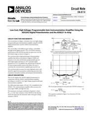
CIRCUIT FUNCTION AND BENEFITS
The circuit shown in Figure 1 provides a low cost, high voltage,
programmable gain instrumentation amplifier using the AD5292
digital potentiometer and the AD8221 instrumentation
amplifier.
The circuit offers 1,024 different gain settings, controllable
through an SPI digital interface. The ±1% resistor tolerance
performance of the AD5292 provides low gain error over the
full resistor range, as shown in Figure 2.
The circuit provides a high performance instrumentation
amplifier that delivers the industry’s highest CMRR over
frequency in its class and dynamic programmable gain for
both single supply operation at +30 V and dual supply
operation at ±15 V. In addition, the AD5292 has an internal
20-times programmable memory that allows the user to
customize the instrumentation amplifier gain at power-up.
The circuit provides accurate, low noise, high gain and is well
suited for signal instrumentation conditioning, precision data
acquisition, biomedical analysis, and aerospace instrumentation.
CIRCUIT DESCRIPTION
This circuit employs the AD5292 digital potentiometer in
conjunction with the AD8221 instrumentation amplifier,
providing an overall low cost, high voltage, programmable gain
instrumentation amplifier.
The differential input signal, +IN and –IN, is amplified by the
AD8221. The instrumentation amplifier offers accuracy, low
noise, high CMRR, and high slew rate.
The maximum circuit gain is defined in Equation 1, where
R
AW _MIN
is the wiper resistance of the AD5292 in the rheostat
mode and represents the minimum value of the gain-setting
resistance (100 Ω).
AD8221
+V
S
–V
S
+15V/+30V
–15V/GND
V
OUT
R
AB
20kΩ
R
AW
AD5292
V
DD
+15V/+30V
V
SS
–15V/GND
SERIAL
INTERFACE
V
REF
+IN
–IN
08433-001
Figure 1. Programmable Gain Instrumentation Amplifier (Simplified
Schematic: Decoupling and All Connections Not Shown)
4
3
2
1
0
0 250 500 750 1000
GAIN ERROR (%)
CODE (Decimal)
08433-002
Figure 2. Gain Error vs. Code
500
4.49
1
4.49
1
_
MINAWAB
R
k
R
k
G
(1)
The circuit gain formula for any particular AD5292 resistance is
1024
)1024(
4.49
1
AB
RD
k
G
(2)
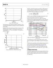
This equation is plotted in Figure 3 as a function of D, the
decimal code.


