

herunterladen
AN-953
APPLICATION NOTE
One Technology Way • P. O. Box 9106 • Norwood, MA 02062-9106, U.S.A. • Te l: 781.329.4700 • Fax: 781.461.3113 • www.analog.com
Direct Digital Synthesis (DDS) with a Programmable Modulus
by Ken Gentile
Rev. B | Page 1 of 4
DAC
ANGLE-TO-
AMPLITUDE
CONVERSION
DPC
C
CC
QD
ACCUMULATOR
07234-001
TUNING
WORD
SAMPLE
CLOCK
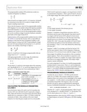
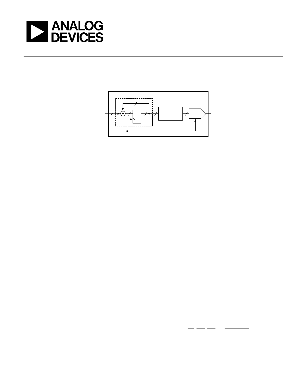
Figure 1. Typical Accumulator-Based DDS Architecture
OVERVIEW
The programmable modulus is a modification of the typical
accumulator-based DDS architecture. It extends the use of DDS
to applications that require exact rational frequency synthesis
(any-rate applications, for example). The AD9913 is the first
accumulator-based DDS product by Analog Devices, Inc., to
offer the programmable modulus architecture.
TYPICAL ACCUMULATOR-BASED DDS
A typical accumulator-based DDS relies on an accumulator to
recursively sum the digital input tuning word at the rate of the
sample clock (see Figure 1). This produces a time series of
digital words at the output of the accumulator that increases
linearly until the accumulator rolls over at its maximum value
of 2
C
. Hence, the accumulator output has a fixed modulus of 2
C
.
Usually the accumulator output is truncated to P bits (using
only the MSBs) to reduce the size and complexity of the angle-
to-amplitude conversion block that immediately follows the
accumulator. This causes the time series of digital words
produced by the accumulator to appear at the input to the
angle-to-amplitude converter as P-bit word(s) ranging in
value from zero to 2
P
− 1.
The angle-to-amplitude converter maps the P-bit word(s) to
one revolution on the unit circle; that is, it linearly maps binary
values from 0 to 2
P
to radian angles from 0 to 2π. This mapping
arrangement allows the angle-to-amplitude converter to trans-
late the P-bit word(s) to D-bit amplitude value(s) (A) in a very
efficient manner.
The translation process relies on the trigonometric relationship
x = sin(2πk/2
P
)
where:
P is the number of bits taken from the accumulator.
k is the binary value of those bits at any given instant.
The value of A for each k is the value of x scaled, offset,
and rounded such that A takes on integer values between
zero and 2
D
− 1.
It is possible to readily extend the angle-to-amplitude conver-
sion function to perform both sine and cosine conversions
concurrently. Therefore, DDSs that offer both conversion
schemes are commonly found.
Following the angle-to-amplitude converter is a D-bit DAC.
It converts the D-bit digital amplitude values produced by the
angle-to-amplitude converter to analog levels. The result is a
sinusoidal waveform at the output of the DAC with a frequency
determined by the average rollover rate of the accumulator.
The following equation expresses the frequency of the sinusoid that
appears at the DAC output for a typical accumulator-based DDS:
S
C
O
f
M
f
2
(1
)
where:
f
O
is the synthesized frequency.
f
S
is the sampling frequency.
M/2
C
is the fractional scale factor (M and C are positive integers).
Normally, M is constrained to be less than 2
C – 1
. Otherwise, the
DDS synthesizes a Nyquist image frequency. The quantity, 2
C
,
is the modulus of the accumulator, where C is the accumulator
width in bits. The integer, M, is often referred to as the frequency
tuning word. Because M, by definition, is an integer, f
O
is
constrained to the following set of frequencies:
C
S
C
C
S
C
S
C
S
O
ffff
f
2
12
,,
2
3
,
2
2
,
2
,0
1
(2)