herunterladen

Atmel-8387G-AVR-ATxmega16A4U-34A4U-64A4U-128A4U-Datasheet_03/2014
Features
High-performance, low-power Atmel
®
AVR
®
XMEGA
®
8/16-bit Microcontroller
Nonvolatile program and data memories
16K - 128KB of in-system self-programmable flash
4K - 8KB boot section
1K - 2KB EEPROM
2K - 8KB internal SRAM
Peripheral Features
Four-channel DMA controller
Eight-channel event system
Five 16-bit timer/counters
Three timer/counters with 4 output compare or input capture channels
Two timer/counters with 2 output compare or input capture channels
High-resolution extensions on all timer/counters
Advanced waveform extension (AWeX) on one timer/counter
One USB device interface
USB 2.0 full speed (12Mbps) and low speed (1.5Mbps) device compliant
32 Endpoints with full configuration flexibility
Five USARTs with IrDA support for one USART
Two Two-wire interfaces with dual address match (I
2
C and SMBus compatible)
Two serial peripheral interfaces (SPIs)
AES and DES crypto engine
CRC-16 (CRC-CCITT) and CRC-32 (IEEE
®
802.3) generator
16-bit real time counter (RTC) with separate oscillator
One twelve-channel, 12-bit, 2msps Analog to Digital Converter
One two-channel, 12-bit, 1msps Digital to Analog Converter
Two Analog Comparators with window compare function, and current sources
External interrupts on all general purpose I/O pins
Programmable watchdog timer with separate on-chip ultra low power oscillator
QTouch
®
library support
Capacitive touch buttons, sliders and wheels
Special microcontroller features
Power-on reset and programmable brown-out detection
Internal and external clock options with PLL and prescaler
Programmable multilevel interrupt controller
Five sleep modes
Programming and debug interfaces
PDI (program and debug interface)
I/O and packages
34 Programmable I/O pins
44 - lead TQFP
44 - pad VQFN/QFN
49 - ball VFBGA
Operating voltage
1.6 – 3.6V
Operating frequency
0 – 12MHz from 1.6V
0 – 32MHz from 2.7V
8/16-bit Atmel XMEGA Microcontroller
ATxmega128A4U / ATxmega64A4U /
ATxmega32A4U / ATxmega16A4U
Verzeichnis
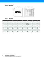
- ・ Konfiguration des Pinbelegungsdiagramms on Seite 3 Seite 33 Seite 54 Seite 57
- ・ Abmessungen des Paketumrisses on Seite 67 Seite 69 Seite 70
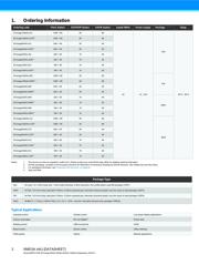
- ・ Teilenummerierungssystem on Seite 2 Seite 12 Seite 335
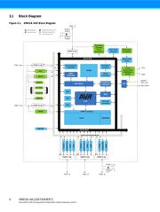
- ・ Blockdiagramm on Seite 3 Seite 6 Seite 9 Seite 54 Seite 335
- ・ Typisches Anwendungsschaltbild on Seite 2
- ・ Beschreibung der Funktionen on Seite 54
- ・ Technische Daten on Seite 71 Seite 92 Seite 114 Seite 136
- ・ Anwendungsbereich on Seite 2 Seite 12 Seite 13 Seite 18 Seite 341
- ・ Elektrische Spezifikation on Seite 14 Seite 71 Seite 336


