
herunterladen
© Semiconductor Components Industries, LLC, 2011
February, 2011 − Rev. 11
1 Publication Order Number:
CAT5110/D
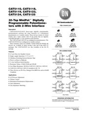
CAT5110, CAT5118,
CAT5119, CAT5123,
CAT5124, CAT5125
32-Tap MiniPott Digitally
Programmable Potentiome-
ters with 2-Wire Interface
Description
CAT5110/18/19/23/24/25 linear−taper digitally programmable
potentiometers perform the same function as a mechanical
potentiometer or a variable resistor. These devices consist of a fixed
resistor and a wiper contact with 32−tap points that are digitally
controlled through a 2−wire up/down serial interface.
The CAT5110 and CAT5125 are configured as potentiometers. The
CAT5118/19/23/24 are configured as variable resistors.
Three resistance values are available: 10 kW, 50 kW and 100 kW. All
devices are available in space−saving 5−pin and 6−pin SOT−23
packages. The CAT5110/18/19 are also available in the SC−70
package.
Features
• 0.3 mA Ultra−low Standby Current
• Single−supply Operation: 2.7 V to 5.5 V
• Glitchless Switching between Resistor Taps
• Power−on Reset to Midscale
• 2−wire Up/Down Serial Interface
• Resistance Values: 10 kW, 50 kW and 100 kW
• Low Wiper Resistance: 80 W for CAT5123, CAT5124, CAT5125
• CAT5110, CAT5118, CAT5119 Available in SC−70
• These Devices are Pb−Free, Halogen Free/BFR Free and are RoHS
Compliant
Applications
• LCD Screen Adjustment
• Volume Control
• Mechanical Potentiometer Replacement
• Gain Adjustment
• Line Impedance Matching
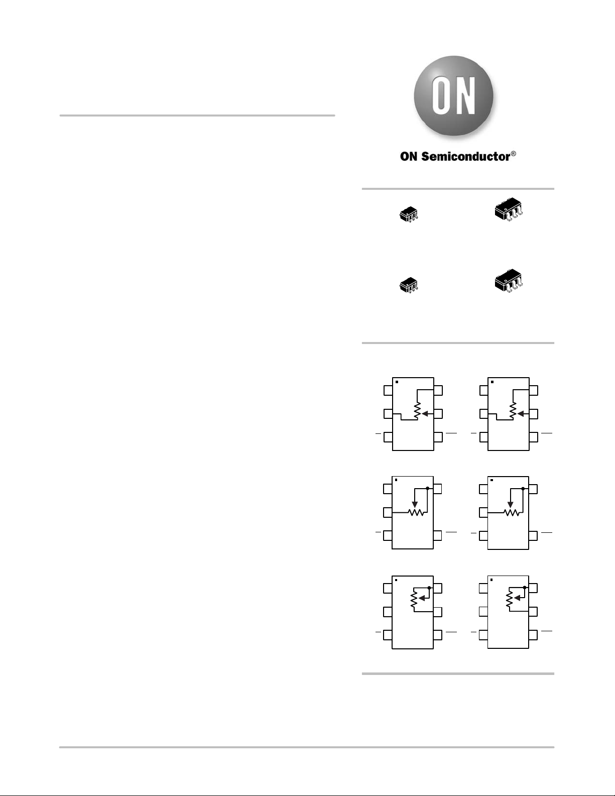
http://onsemi.com
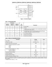
SC−70
SD SUFFIX
CASE 419AD
PIN CONNECTIONS
(Top Views)
SOT−23
TB SUFFIX
CASE 527AJ
SC−70
SD SUFFIX
CASE 419AC
SOT−23
TB SUFFIX
CASE 527AH
See detailed ordering and shipping information in the package
dimensions section on page 11 of this data sheet.
ORDERING INFORMATION
GND
1
6
H
2
3
4
W
5
CAT5110
CAT5125
SOT−23
GND
16
H
2
34
W
5
CAT5110
SC−70
GND
H
2
CAT5118
CAT5123
15
34
GND
H
2
CAT5118
15
34
GND
H
L
5
34
GND
16H
2
L5
CAT5119
CAT5124
34
2
CAT5119
16
U/D
V
DD
CS
CS
V
DD
U/D
SOT−23
SC−70
SOT−23
SC−70
CS
CS
V
DD
V
DD
U/D
CS
U/D
V
DD
CS
U/D U/D
V
DD
Verzeichnis
- ・ Konfiguration des Pinbelegungsdiagramms on Seite 1 Seite 2
- ・ Abmessungen des Paketumrisses on Seite 7 Seite 8 Seite 9 Seite 10
- ・ Teilenummerierungssystem on Seite 1 Seite 11 Seite 12
- ・ Typisches Anwendungsschaltbild on Seite 2
- ・ Beschreibung der Funktionen on Seite 5
- ・ Technische Daten on Seite 2 Seite 12
- ・ Anwendungsbereich on Seite 1 Seite 6
- ・ Elektrische Spezifikation on Seite 3