

herunterladen
CAT9532
© Catalyst Semiconductor, Inc. 1 Doc. No. MD-9001 Rev. C
Characteristics subject to change without notice
16-bit Programmable LED Dimmer with I
2
C Interface
FEATURES
16 LED drivers with dimming control
256 brightness steps
16 open drain outputs drive 25 mA each
2 selectable programmable blink rates:
– frequency: 0.593Hz to 152Hz
– duty cycle: 0% to 99.6%
I/Os can be used as GPIOs
400kHz I
2
C bus compatible*
2.3V to 5.5V operation
5V tolerant I/Os
Active low reset input
RoHS-compliant 24-Lead SOIC, TSSOP and
24-pad TQFN (4 x 4mm) packages
APPLICATIONS
Backlighting
RGB color mixing
Sensors control
Power switches, push-buttons
Alarm systems
DESCRIPTION
The CAT9532 is a CMOS device that provides 16-bit
parallel input/output port expander optimized for LED
dimming control. The CAT9532 outputs can drive
directly 16 LEDs in parallel. Each individual LED may
be turned ON, OFF, or blinking at one of two
programmable rates. The device provides a simple
solution for dimming LEDs in 256 brightness steps for
backlight and color mixing applications. The CAT9532
is suitable in I
2
C and SMBus compatible applications
where it is necessary to limit the bus traffic or free-up
the bus master’s timer.
The CAT9532 contains an internal oscillator and two
PWM signals that drive the LED outputs. The user can
program the period and duty cycle for each individual
PWM signal. After the initial set-up command to
program the Blink Rate 1 and Blink Rate 2 (frequency
and duty cycle), only one command from the bus master
is required to turn each individual open drain output ON,
OFF, or cycle at Blink Rate 1 or Blink Rate 2. Each
open drain LED output can provide a maximum output
current of 25mA. The total current sunk by all I/Os must
not exceed 200mA.
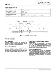
TYPICAL APPLICATION CIRCUIT
For Ordering Information details, see page 16.
Notes: LED0 to LED11 are used as LED drivers
LED12 to LED15 are used as regular GPIOs
* Catalyst Semiconductor is licensed by Philips Corporation to
carry the I
2
C Protocol.
CAT9532
GPIOs
I
2
C/SMBus
Master
V
SS
A0
A1
A2
RS03 x 10kΩ RS1 RS11
5 V
LED11
LED1
LED0
V
CC
LED12
LED15
SDA
5 V
SCL
SDA
SCL
RESET
RESET
Verzeichnis
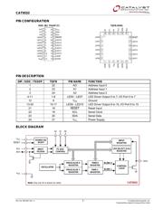
- ・ Konfiguration des Pinbelegungsdiagramms on Seite 2 Seite 6
- ・ Abmessungen des Paketumrisses on Seite 13
- ・ Teilenummerierungssystem on Seite 1 Seite 16
- ・ Blockdiagramm on Seite 2
- ・ Typisches Anwendungsschaltbild on Seite 1 Seite 12
- ・ Beschreibung der Funktionen on Seite 7
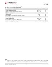
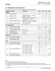
- ・ Technische Daten on Seite 3
- ・ Anwendungsbereich on Seite 1