

herunterladen
August 2015
© 2010 Fairchild Semiconductor Corporation www.fairchildsemi.com
FAN53555 • Rev. 1.14
FAN53555 — 5 A, 2.4 MHz, Digitally Programmable TinyBuck™ Regulator
FAN53555
5 A, 2.4 MHz, Digitally Programmable TinyBuck
®
Regulator
Features
Fixed-Frequency Operation: 2.4 MHz
Best-in-Class Load Transient
Continuous Output Current Capability: 5 A
Pulse Current Capability: 6.5 A (05 Option)
2.5 V to 5.5 V Input Voltage Range
Digitally Programmable Output Voltage:
- 00/01/03/05/08/18 Options: 0.6-1.23 V in 10 mV Steps
- 04/042/09/ Options: 0.603-1.411 V in 12.826 mV Steps
- 23 Option: 0.60-1.3875 V in 12.5 mV Steps
- 24 Option: 0.603-1.420 V in 12.967 mV Steps
- 13 Option: 0.8-1.43 V in 10 mV Steps
Programmable Slew Rate for Voltage Transitions
I
2
C-Compatible Interface Up to 3.4 Mbps
PFM Mode for High Efficiency in Light Load
Quiescent Current in PFM Mode: 60 µA (Typical)
Internal Soft-Start
Input Under-Voltage Lockout (UVLO)
Thermal Shutdown and Overload Protection
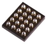
20-Bump Wafer-Level Chip Scale Package (WLCSP)
Applications
Application, Graphic, and DSP Processors
- ARM™, Krait™, OMAP™, NovaThor™, ARMADA™
Hard Disk Drives
Tablets, Netbooks, Ultra-Mobile PCs
Smart Phones
Gaming Devices
All trademarks are the property of their respective owners.
Description
The FAN53555 is a step-down switching voltage regulator
that delivers a digitally programmable output from an input
voltage supply of 2.5 V to 5.5 V. The output voltage is
programmed through an I
2
C interface capable of operating up
to 3.4 MHz.
Using a proprietary architecture with synchronous
rectification, the FAN53555 is capable of delivering 5 A
continuous at over 80% efficiency, while maintaining over
80% efficiency at load currents as low as 10 mA. Pulse
currents as high as 6.5 A can be supported by the 05 option.
The regulator operates at a nominal fixed frequency of
2.4 MHz, which reduces the value of the external components
to 330 nH for the output induction and as low as 20 µF for the
output capacitor. Additional output capacitance can be added
to improve regulation during load transients without affecting
stability. Inductance up to 1.2 µH may be used with additional
output capacitance.
At moderate and light loads, Pulse Frequency Modulation
(PFM) is used to operate in Power-Save Mode with a typical
quiescent current of 60 µA. Even with such a low quiescent
current, the part exhibits excellent transient response during
large load swings. At higher loads, the system automatically
switches to fixed-frequency control, operating at 2.4 MHz. In
Shutdown Mode, the supply current drops below 1 µA,
reducing power consumption. PFM Mode can be disabled if
constant frequency is desired. The FAN53555 is available in a
20-bump, 1.6 x 2 mm, WLCSP.
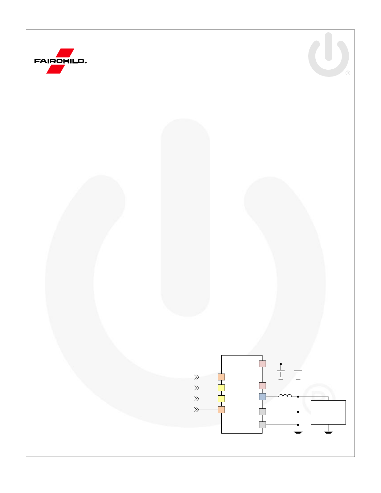
FAN53555
SW
C
OUT
L1
PVIN
GND
C
IN
VOUT
C
IN1
AGND
Core
Processor
(System Load)
GND
VDD
VSEL
SCL
SDA
EN
Figure 1. Typical Application
Verzeichnis
- ・ Konfiguration des Pinbelegungsdiagramms on Seite 4
- ・ Paket-Footprint-Pad-Layout on Seite 25
- ・ Teilenummerierungssystem on Seite 2
- ・ Blockdiagramm on Seite 26
- ・ Typisches Anwendungsschaltbild on Seite 1
- ・ Technische Daten on Seite 5 Seite 8 Seite 9 Seite 29
- ・ Anwendungsbereich on Seite 1 Seite 3
- ・ Elektrische Spezifikation on Seite 6 Seite 7