


herunterladen

LM26480
LDO1_FB
VOUTLDO2
GND_L
VOUTLDO1
ENLDO1
LDO2_FB
VIN1
SW1
FB1
VINLDO2
SW2
FB2
VIN2
GND_SW2
10 µF
ENSW1
2.2 µH
ENSW2
GND_SW1
VINLDO1
SYNC
nPOR
ENLDO2
GND_C
AVDD
VINLDO12
R1
R2
0.47 µF
0.47 µF
1 µF
R2
R1
1 µF
10 µF
R2
C2
C1
R1
R1
10 µF
2.2 µH
10 µF
1 µF
R2
C1
C2
1 µF
100 k
DAP
Product
Folder
Sample &
Buy
Technical
Documents
Tools &
Software
Support &
Community
LM26480
SNVS543K –JANUARY 2008–REVISED JANUARY 2015
LM26480 Externally Programmable Dual High-Current Step-Down DC-DC and Dual Linear
Regulators
1 Features 2 Applications
1
• Input Voltage: 2.8 V to 5.5 V
• Core Digital Power
• Compatible with Advanced Applications • Applications Processors
Processors and FPGAs
• Peripheral I/O Power
• Two LDOs for Powering Internal Processor
3 Description
Functions and I/Os
The LM26480 is a multi-functional Power
• Precision Internal Reference
Management Unit, optimized for low-power digital
• Thermal Overload Protection
applications. This device integrates two highly
• Current Overload Protection
efficient 1.5-A step-down DC-DC converters and two
• External Power-On-Reset Function for Buck1 and
300-mA linear regulators.
Buck2
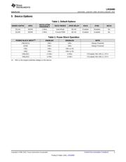
Device Information
(1)
• Undervoltage Lockout Detector to Monitor Input
PART NUMBER PACKAGE BODY SIZE (NOM)
Supply Voltage
LM26480 WQFN (24) 4.00 mm x 4.00 mm
• Step-Down DC-DC Converter (Buck)
(1) For all available packages, see the orderable addendum at
– 1.5-A Output Current
the end of the datasheet.
– V
OUT
from:
space
– Buck1 : 0.8 V to 2 V at 1.5 A
space
– Buck2 : 1 V to 3.3 V at 1.5 A
space
– Up to 96% efficiency
– ±3% FB voltage accuracy
space
– 2-MHz PWM switching frequency
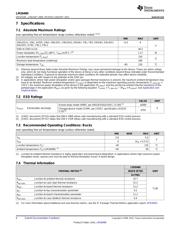
Simplified Schematic
– PWM-to-PFM Automatic Mode Change under
Low Loads
– Automatic Soft Start
• Linear Regulators (LDO)
– V
OUT
of 1 V to 3.5 V
– ±3% FB Voltage Accuracy
– 300-mA Output Current
– 25-mV (typ) Dropout
1
An IMPORTANT NOTICE at the end of this data sheet addresses availability, warranty, changes, use in safety-critical applications,
intellectual property matters and other important disclaimers. PRODUCTION DATA.
Verzeichnis
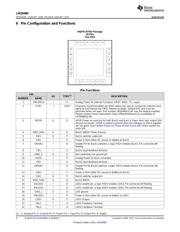
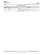
- ・ Konfiguration des Pinbelegungsdiagramms on Seite 4 Seite 5
- ・ Abmessungen des Paketumrisses on Seite 36 Seite 38 Seite 39
- ・ Markierungsinformationen on Seite 36
- ・ Blockdiagramm on Seite 1 Seite 14 Seite 15 Seite 23
- ・ Typisches Anwendungsschaltbild on Seite 25 Seite 26 Seite 27
- ・ Beschreibung der Funktionen on Seite 15 Seite 17
- ・ Technische Daten on Seite 6 Seite 7
- ・ Anwendungsbereich on Seite 1 Seite 42
- ・ Elektrische Spezifikation on Seite 7 Seite 9