Web Analytics
Datasheet
Teiledatenblatt > Active Filter > Maxim Integrated > MAX270CWP+ Datenblatt-PDF > MAX270CWP+ Programmierhandbuch Seite 1/2
MAX270CWP+
€ 13.36
Preis von AiPCBA

MAX270CWP+ Programmierhandbuch - Maxim Integrated

  • Hersteller:
    Maxim Integrated
  • Kategorie:
    Active Filter
  • Fallpaket
    SOIC-20
  • Beschreibung:
    Active Filter Dual Continuous Time Low Pass 4th Order 25kHz 20Pin SOIC W
Aktualisierte Uhrzeit: 2025-05-12 01:18:00 (UTC+8)

MAX270CWP+ Programmierhandbuch

Seite:von 2
PDF herunterladen
Neu laden
herunterladen
Maxim > Design Support > Technical Documents > Application Notes > Filter Circuits (Analog) > APP 23
Keywords: analog filter, microprocessor supervisor, uP supervisor, reset circuit, power fail comparator
APPLICATION NOTE 23
µP-Supervisor Chip Controls Programmable Filter
Jul 09, 1998
Abstract: An application showing how the use of a microprocessor supervisor can be used to program a dual
section filter. Using the time delay from the reset circuit and strapping it to the power-fail comparator with a
delay circuit, the filter can easily be programmed to provide the correct cutoff frequencies during power up
using this reset circuit.
Certain dual-section filter ICs have a common 7-bit port for programming the two cutoff frequencies (f
C
). If
both sections require the same f
C
, you can strap an appropriate code to the port pins, but other applications
require a different f
C
for each section. In such cases, a microprocessor is the obvious tool for sequentially
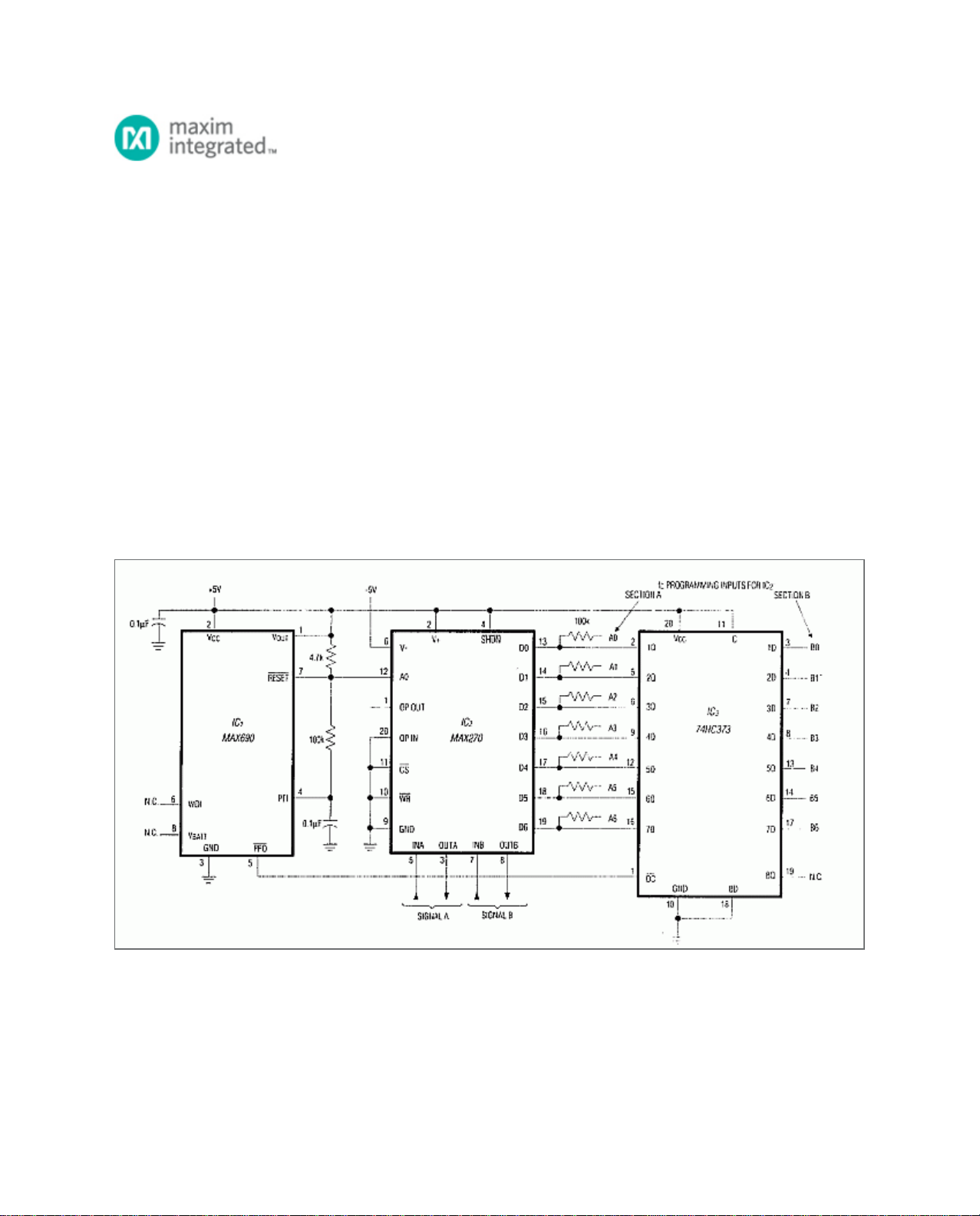
programming the two filter sections, but lacking a µP, you can do the job without the circuit of Figure 1.
Figure 1. A µP-supervisory chip (IC1) directs the sequential loading of f
C
data into the dual, programmable
lowpass filter IC2. The circuit reloads this f
C
data following each power-up.
IC
2
is a continuous, dual-lowpass filter containing identical 2nd-order sections A and B. To program desired f
C
values, obtain corresponding codes from the data sheet and connect each pin of A0-A6 and B0-B6 to 5V ("1")
or GND ("0") accordingly. (The latches internal to inputs D0-D6 remain "transparent" because inputs active-low
Page 1 of 2

MAX270CWP+ Datenblatt-PDF

MAX270CWP+ Datenblatt PDF
Maxim Integrated
16 Seiten, 1317 KB
MAX270CWP+ Programmierhandbuch
Maxim Integrated
2 Seiten, 65 KB
MAX270CWP+ Anderes Datenblatt
Maxim Integrated
7 Seiten, 106 KB
MAX270CWP+ Anwendungshinweis
Maxim Integrated
3 Seiten, 80 KB

MAX270 Datenblatt-PDF

MAX270
Datenblatt PDF
Maxim Integrated
Digitally Programmable, Dual, 2nd-Order, Continuous Lowpass Filter
MAX270CPP+
Datenblatt PDF
Maxim Integrated
Active Filter Dual Continuous Time Low Pass 4th Order 25kHz 20Pin PDIP N
MAX270EWP+
Datenblatt PDF
Maxim Integrated
Active Filter Dual Continuous Time Low Pass 4th Order 25kHz 20Pin SOIC W
MAX270CPP
Datenblatt PDF
Maxim Integrated
Active Filter Dual Continuous Time Low Pass 4th Order 25kHz 20Pin PDIP N
MAX270EWP+T
Datenblatt PDF
Maxim Integrated
Active Filter Dual Continuous Time Low Pass 4th Order 25kHz 20Pin SOIC W T/R
MAX270CWP+
Datenblatt PDF
Maxim Integrated
Active Filter Dual Continuous Time Low Pass 4th Order 25kHz 20Pin SOIC W
MAX270EPP+
Datenblatt PDF
Maxim Integrated
Active Filter Dual Continuous Time Low Pass 4th Order 25kHz 20Pin PDIP N
MAX270CWP+T
Datenblatt PDF
Maxim Integrated
Ic Filter Lowpass Prog 20-Soic
MAX270EWP-T
Datenblatt PDF
Maxim Integrated
Continuous Time Filter, 2 Func, Digitally Programmable, Lowpass, CMOS, PDSO20, SO-20
MAX270CWP
Datenblatt PDF
Maxim Integrated
Active Filter Dual Continuous Time Low Pass 4th Order 25kHz 20Pin SOIC W
Datenblatt-PDF-Suche
Suche
100 Millionen Datenblatt-PDF, aktualisieren Sie mehr als 5.000 PDF-Dateien pro Tag.
Kontakt online
Bonnie - AiPCBA Sales Manager Online, vor 5 Minuten
Ihre E-Mail *
Nachricht *
Senden