herunterladen

2002 Microchip Technology Inc. DS30262E-page 1
M
PIC16F8X
This document includes the
programming specifications for the
following devices:
•PIC16F83
• PIC16CR83
•PIC16F84
• PIC16CR84
•PIC16F84A
1.0 PROGRAMMING THE PIC16F8X
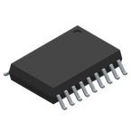
The PIC16F8X devices are programmed using a serial
method. The Serial mode will allow these devices to be
programmed while in the user’s system. This allows for
increased design flexibility. This programming specifi-
cation applies to only the above devices in all
packages.
1.1 Hardware Requirements
The PIC16F8X devices require one programmable
power supply for V
DD (4.5V to 5.5V) and a VPP of 12V
to 14V. Both supplies should have a minimum resolu-
tion of 0.25V.
1.2 Programming Mode
The Programming mode for the PIC16F8X devices
allows programming of user program memory, data
memory, special locations used for ID, and the config-
uration word. On PIC16CR8X devices, only data
EEPROM and CDP can be programmed.
Pin Diagram
RA1
RA0
OSC1/CLKIN
OSC2/CLKOUT
V
DD
RB7
RB6
RB5
RB4
RA2
RA3
RA4/T0CKI
MCLR
VSS
RB0/INT
RB1
RB2
RB3
•1
2
3
4
5
6
7
8
9
18
17
16
15
14
13
12
11
10
PIC16F8X
PDIP, SOIC
TABLE 1-1: PIN DESCRIPTIONS (DURING PROGRAMMING): PIC16F8X
Pin Name
During Programming
Function Pin Type Pin Description
RB6 CLOCK I Clock Input
RB7 DATA I/O Data Input/Output
MCLR
VTEST MODE P
(1)
Program Mode Select
VDD VDD P Power Supply
VSS VSS P Ground
Legend: I = Input, O = Output, P = Power
Note 1: In the PIC16F8X, the programming high voltage is internally generated. To activate the Programming
mode, high voltage needs to be applied to MCLR
input. Since the MCLR is used for a level source, this
means that MCLR
does not draw any significant current.
EEPROM Memory Programming Specification
Verzeichnis

