


herunterladen

'LS292
1
4
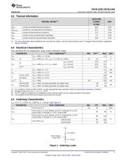
CLK1
5
CLK2
n = 0
n = 1
f
i
11
CLR
3
TP1
6
TP2
13
TP3
7
Q
10
A
i
n
f
2
é ù
ê ú
ë û
1
B
15
C
14
D
2
E
0
4
0
n
31
é ù
ë û
R
i
o
n
f
f
2
é ù
ê ú
ë û
Product
Folder
Sample &
Buy
Technical
Documents
Tools &
Software
Support &
Community
SN74LS292
,
SN74LS294
SDLS153A –JANUARY 1981–REVISED JANUARY 2016
SN74LS29x Programmable Frequency Dividers and Digital Timers
1 Features 3 Description
The SN74LS29x devices are programmable
1
• Count Divider Chain
frequency dividers and digital timers contain 31 flip-
• Digitally Programmable from 2
2
to 2
n
flops plus 30 gates (in SN74LS292) or 15 flip-flops
(n = 31 for SN74LS292 , n = 15 for SN74LS294)
plus 29 gates (in SN74LS294) on a single chip. The
• Useable Frequency Range from DC to 30 MHz
count modulo is under digital control of the inputs
provided.
• Easily Expandable
Both types feature an active-low CLR clear input to
2 Applications
initialize the state of all flip-flops. To facilitate the
incoming inspection, test points are provided (TP1,
• Frequency Division
TP2, and TP3 on the SN74LS292, and TP on the
• Digital Timing
SN74LS294). These test points are not intended to
drive system loads. Both types feature two clock
inputs; either one may be used for clock gating (see
Table 1).
A brief look at the digital timing capabilities of the
SN74LS292 shows that with a 1-MHz input
frequency, programming for 2
10
gives a period of
1.024 ms, 2
20
gives a period of 1.05 sec, 2
26
gives a
period of 1.12 min, and 2
31
gives a period of 35.79
min.
These devices are easily cascadable, giving limitless
possibilities to achievable timing delays.
Device Information
(1)
PART NUMBER PACKAGE BODY SIZE (NOM)
SN74LS292N
PDIP (16) 6.35 mm × 19.30 mm
SN74LS294N
(1) For all available packages, see the orderable addendum at
the end of the data sheet.
Logic Symbols
1
An IMPORTANT NOTICE at the end of this data sheet addresses availability, warranty, changes, use in safety-critical applications,
intellectual property matters and other important disclaimers. PRODUCTION DATA.
Verzeichnis
- ・ Konfiguration des Pinbelegungsdiagramms on Seite 3 Seite 4
- ・ Abmessungen des Paketumrisses on Seite 16
- ・ Markierungsinformationen on Seite 16
- ・ Blockdiagramm on Seite 10
- ・ Typisches Anwendungsschaltbild on Seite 7 Seite 8 Seite 9 Seite 13 Seite 14
- ・ Technische Daten on Seite 4
- ・ Anwendungsbereich on Seite 1
- ・ Elektrische Spezifikation on Seite 5