


herunterladen

Freescale Semiconductor
Application Note
Document Number: AN3797
Rev. 0, 03/2009
Contents
© Freescale Semiconductor, Inc., 2008. All rights reserved.
1 Introduction
The purpose of the integrated programmable interrupt
controller (IPIC) is to receive interrupt requests from the
peripheral modules of a microcontroller, prioritize these
interrupts through the use of various programmable
registers, and provide the vector number of the current
highest priority pending interrupt. Generally speaking,
most of the interrupts can be individually masked. In
some cases an interrupt from a peripheral module can be
programmed to cause different types of interrupts
(normal, system management, and critical) to the CPU
core.
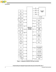
It is important to know the IPIC is a standard module. A
block diagram of the IPIC is shown in Figure 1. The IPIC
can receive 128 interrupting sources and prioritize them
according to how various registers within the IPIC are
programmed. In the present example, using the
MPC5121e, only 56 interrupting sources are brought into
the IPIC module.
1 Introduction . . . . . . . . . . . . . . . . . . . . . . . . . . . . . . . . . . . 1
2 Register Summary. . . . . . . . . . . . . . . . . . . . . . . . . . . . . 17
3 Programming Example Steps . . . . . . . . . . . . . . . . . . . . 20
3.1 Assign the Relative Priorities of the Interrupts in. . 20
3.2 System Global Interrupt Configuration Register . . 26
4 Using the IPIC Control and Status Registers . . . . . . . . 28
5 Forcing Interrupts . . . . . . . . . . . . . . . . . . . . . . . . . . . . . 29
6 Summary . . . . . . . . . . . . . . . . . . . . . . . . . . . . . . . . . . . . 30
Understanding the Integrated
Programmable Interrupt
Controller (IPIC)
by: Charles Melear
Application Engineer, Automotive
Austin, Texas