
herunterladen
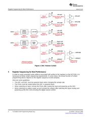
1 Controlling the AIC3104
2 Determining Sample Rate and Master Clock Frequency
Application Report
SLAA403 – February 2009
TLV320AIC3104 Programming Made Easy
David K. Wilson ............................................................................................. Audio Converter Products
ABSTRACT
The TLV320AIC3104 (AIC3104) is a versatile audio codec with multiple features. When
first designing with the AIC3104, reading the entire data sheet and becoming familiar
with the entire register set can be a daunting task. However, in many common
configurations, it is possible to get the AIC3104 up and running while only writing to as
few as 12 registers.
Although not intended to replace the data sheet, this document details several common
configurations for the AIC3104. It gives a concise description of how to set up the
codec and gives a script example that can be used to accelerate your design.
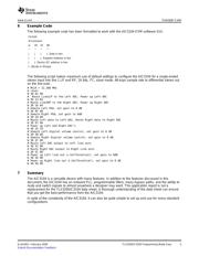
All features of the AIC3104 are accessed by programmable registers. The registers can be programmed
by an external microprocessor or DSP using I
2
C™ protocol. The master clock (MCLK) is not required to
be running while programming the AIC3104. The fixed 7-bit I
2
C address for the AIC3104 is 001 1000
(0x30h to write, 0x31h to read). The AIC3104 supports I
2
C data rates up to 400 kHz.
It is good practice to perform a hardware reset after initial power up to ensure that all registers are in their
default states and that the AIC3104 is ready to be programmed.
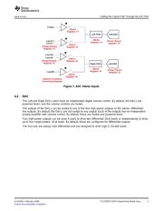
The first task for any design using the AIC3104 is to determine the desired sample rate and master clock
frequency. With the exception of register programming, all internal timing, including the sample rate, is
ultimately derived from an external master clock. By default, the ADC and DAC sample rates are
MCLK/256. For the common audio sample rates 44.1 ksps and 48 ksps, the most common MCLK
frequencies are 11.2896 MHz (44.1 ksps × 256) and 12.288 MHz (48 ksps × 256). If you are using one of
these two MCLK frequencies and sample rates, no register programming is needed to set the sample rate.
Table 1 shows two common audio MCLK frequencies and the settings required to obtain common sample
rates.
Table 1. MCLK Frequencies and Settings
DESIRED SAMPLE RATE REGISTER SETTINGS
MCLK = 11.2896 MHz
44.1 ksps None Required (use defaults)
MCLK = 12.288 MHz
48 ksps None Required (use defaults)
8 ksps Register 2, Page 0 = 0xAA
16 ksps Register 2, Page 0 = 0x44
32 ksps Register 2, Page 0 = 0x11
96 ksps Register 7, Page 0, D6 and D5 = 1
I
2
C is a trademark of Koninklijke Philips Electronics NV.
SLAA403 – February 2009 TLV320AIC3104 Programming Made Easy 1
Submit Documentation Feedback