


herunterladen

Application Report
SNOA554C–October 2011–Revised May 2013
AN-2090 LM3448 -120VAC, 6W Isolated Flyback LED
Driver
.....................................................................................................................................................
ABSTRACT
This application note describes the performance of a LM3448 based Flyback LED driver solution that can
be used to power a single LED string consisting of seven to eleven series connected LEDs from a 85 V
RMS
to 135 V
RMS
, 60 Hz input power supply.
Contents
1 Introduction .................................................................................................................. 3
2 Key Features ................................................................................................................ 3
3 Applications .................................................................................................................. 3
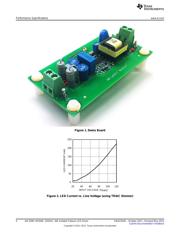
4 Performance Specifications ................................................................................................ 3
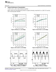
5 Typical Performance Characteristics ..................................................................................... 5
6 EMI Performance ........................................................................................................... 6
7 Circuit Operation With Forward Phase TRIAC Dimmer ................................................................ 7
8 Circuit Operation With Reverse Phase TRIAC Dimmer ............................................................... 8
9 Thermal Performance ...................................................................................................... 9
10 LM3448 Device Pin-Out .................................................................................................. 11
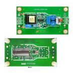
11 Demo Board Wiring Overview ........................................................................................... 12
12 Demo Board Assembly ................................................................................................... 12
13 Design Guide ............................................................................................................... 14
13.1 DCM Flyback Converter ......................................................................................... 15
13.2 Transformer ....................................................................................................... 18
13.3 Bias Supplies and Capacitances ............................................................................... 21
13.4 COFF Current Source ........................................................................................... 23
13.5 TRIAC Holding Circuit ........................................................................................... 24
13.6 Overvoltage Protection .......................................................................................... 24
13.7 Input Filter ......................................................................................................... 25
13.8 Inrush Limiting and Damping ................................................................................... 26
14 Design Calculations ....................................................................................................... 27
14.1 Specifications ..................................................................................................... 27
14.2 Preliminary Calculations ......................................................................................... 27
14.3 SW FET ............................................................................................................ 28
14.4 Current Sense ..................................................................................................... 28
14.5 Recirculating Diode ............................................................................................... 29
14.6 Transformer ....................................................................................................... 29
14.7 COFF Current Source ........................................................................................... 30
14.8 PassFET ........................................................................................................... 30
14.9 Input Capacitance ................................................................................................ 30
14.10 Output Capacitance .............................................................................................. 31
14.11 Overvoltage Protection Zener Diode .......................................................................... 31
14.12 Transil Clamp ..................................................................................................... 31
15 Evaluation Board Schematic ............................................................................................. 32
16 Transformer Design ....................................................................................................... 35
17 PCB Layout ................................................................................................................. 36
All trademarks are the property of their respective owners.
1
SNOA554C–October 2011–Revised May 2013 AN-2090 LM3448 -120VAC, 6W Isolated Flyback LED Driver
Submit Documentation Feedback
Copyright © 2011–2013, Texas Instruments Incorporated
Verzeichnis