
herunterladen
1
SNVA768–December 2016
Submit Documentation Feedback
Copyright © 2016, Texas Instruments Incorporated
Analog PWM Dimming in White-LED Drivers
Application Report
SNVA768–December 2016
Analog PWM Dimming in White-LED Drivers
TravisEichhorn
ABSTRACT
Pulse-width modulation (PWM) is a common type of dimming used to adjust the current in white-LED
driver devices. PWM dimming takes a rectangle waveform with variable positive duty cycle (D) and adjusts
the LED current proportionally. For many smaller format white LED drivers (7-inch screen size or smaller),
the PWM signal is converted to a DC control voltage and made to drive the LED current in a DC (or
analog) method. This application note discusses some of the benefits and drawbacks of a PWM-to-analog
dimming method.
Contents
1 PWM Dimming ............................................................................................................... 2
2 PWM-to-Analog Methods................................................................................................... 2
List of Figures
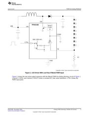
1 LED Driver With Low-Pass-Filtered PWM Input......................................................................... 3
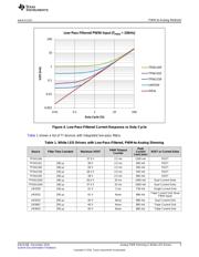
2 TPS61165 (Low-Pass-Filtered PWM) Waveforms ...................................................................... 4
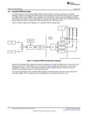
3 Offset Error in Feedback Voltage.......................................................................................... 4
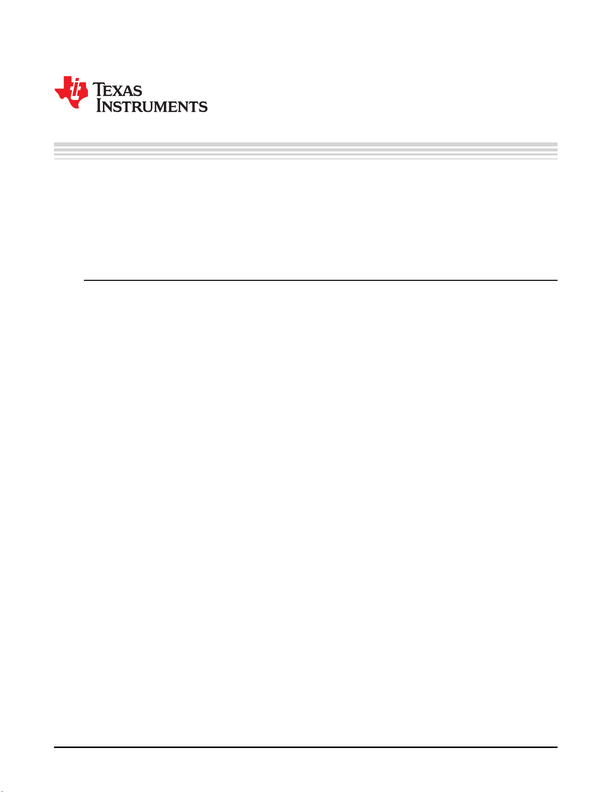
4 Low-Pass-Filtered Current Response vs Duty Cycle ................................................................... 5
5 Sampled PWM-to-Analog Block Diagram ................................................................................ 6
6 Sampled PWM Current Response vs Duty Cycle....................................................................... 7
7 PWM Sample Rate Options (LM36923x Devices) ...................................................................... 8
8 Determining PWM Hysteresis Based on Jitter........................................................................... 9
9 LED Current-Mapping-Mode Options.................................................................................... 10
10 LED Current Ramping With Duty Cycle Changes ..................................................................... 11
11 Increasing PWM Resolution With Automatic Ramping................................................................ 12
List of Tables
1 White LED Drivers with Low-Pass-Filtered, PWM-to-Analog Dimming............................................... 5
2 White LED Drivers With Sampled PWM-to-Analog Dimming.......................................................... 7
3 Programmable Sample Frequencies (LM3692x Devices).............................................................. 8
4 Programmable Hysteresis Options (LM3692x Devices)................................................................ 9
5 Devices With Ramping Between PWM Duty Cycle Changes ........................................................ 13
Trademarks
All trademarks are the property of their respective owners.
Verzeichnis
- ・ Blockdiagramm on Seite 6
- ・ Beschreibung der Funktionen on Seite 7
- ・ Anwendungsbereich on Seite 14