


herunterladen
LM3557
-+
R2
L
2.2 PH
Cin
4.7 PF
Cout
1 PF
NC
V
IN
En
Gnd
Fb
Sw2
OvpSw1
D
V
SUPPLY
Vout
LM3557
www.ti.com
SNVS338B –NOVEMBER 2004–REVISED FEBRUARY 2013
LM3557 Step-Up Converter for White LED Applications
Check for Samples: LM3557
1
FEATURES
DESCRIPTION
The LM3557 is a complete solution for white LED
2
• V
IN
Range: 2.7V–7.5V
drive applications. With minimal external component
• Small External Components
count, no DC current leakage paths to ground, cycle-
• 1.25 MHz Constant-Switching Frequency
by-cycle current limit protection, and output over-
voltage protection circuitry, the LM3557 offer superior
• Output Over-Voltage Protection
performance and cost savings over standard DC/DC
• Input Under-Voltage Protection
boost component implementations.
• Cycle-By-Cycle Current Limit
The LM3557 switches at a fixed-frequency of 1.25
• TRUE SHUTDOWN: No DC current paths to
MHz, which allows for the use of small external
ground during shutdown
components. Also, the LM3557 has a wide input
• Low Profile Package: <1 mm Height -8 Pin
voltage range to take advantage of multi-cell input
applications. With small external components, high
WSON
fixed frequency operation, and wide input voltage
• No External Compensation
range, the LM3557 is the most optimal choice for
LED lighting applications.
APPLICATIONS
• White LED Display Lighting
• Cellular Phones
• PDAs
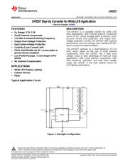
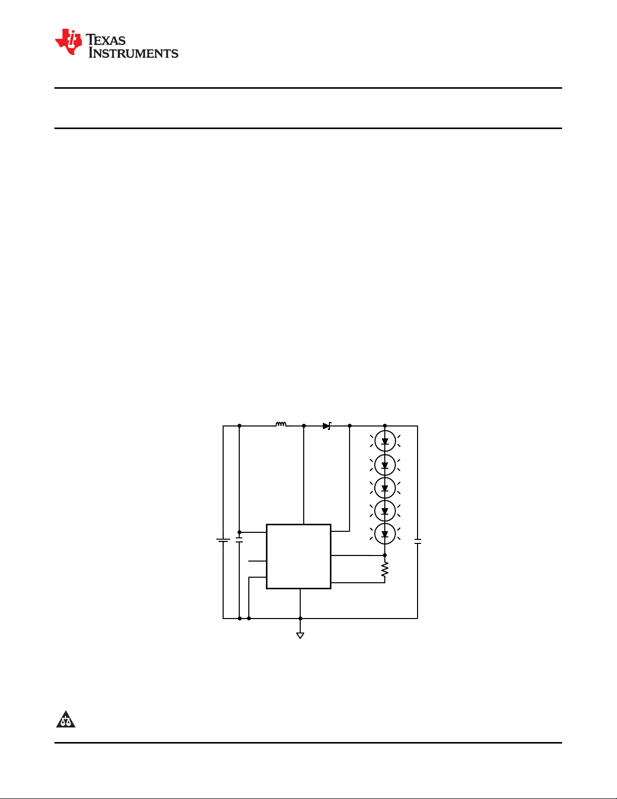
Typical Application Circuit
Figure 1. Backlight Configuration
1
Please be aware that an important notice concerning availability, standard warranty, and use in critical applications of
Texas Instruments semiconductor products and disclaimers thereto appears at the end of this data sheet.
2All trademarks are the property of their respective owners.
PRODUCTION DATA information is current as of publication date.
Copyright © 2004–2013, Texas Instruments Incorporated
Products conform to specifications per the terms of the Texas
Instruments standard warranty. Production processing does not
necessarily include testing of all parameters.
Verzeichnis
- ・ Konfiguration des Pinbelegungsdiagramms on Seite 2
- ・ Abmessungen des Paketumrisses on Seite 14 Seite 16 Seite 17
- ・ Markierungsinformationen on Seite 14
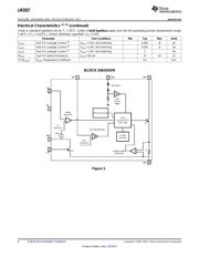
- ・ Blockdiagramm on Seite 4
- ・ Typisches Anwendungsschaltbild on Seite 1
- ・ Technische Daten on Seite 2 Seite 3
- ・ Anwendungsbereich on Seite 1 Seite 12 Seite 19
- ・ Elektrische Spezifikation on Seite 2 Seite 3 Seite 4 Seite 6 Seite 7